Search This Blog

Tuesday 24 February 2015

MEP Pressure Drop and Duct & Pipe System Calculations

Let's have a look at the native Pressure Drop calculation methods that takes place in Revit. 

For ducting, we can choose between 3 calculation methods:
1. Altshul-Tsal Equation
2. Colebrook Equation
3. Haaland Equation

It is possible to use a different calculation method for straight duct segment pressure drops, through the API, or alternatively, to download a calculation method from a third-party developer.


The Altshul-Tsal Equation provides a pressure drop for, as an example, the 225x225 duct segment, of 3.85 Pa

The Colebrook Equation provides a pressure drop for the 225x225 duct segment, of 3.81 Pa

The Haaland Equation provides a pressure drop for the 225x225 duct segment, of 3.65 Pa

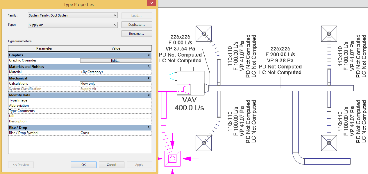
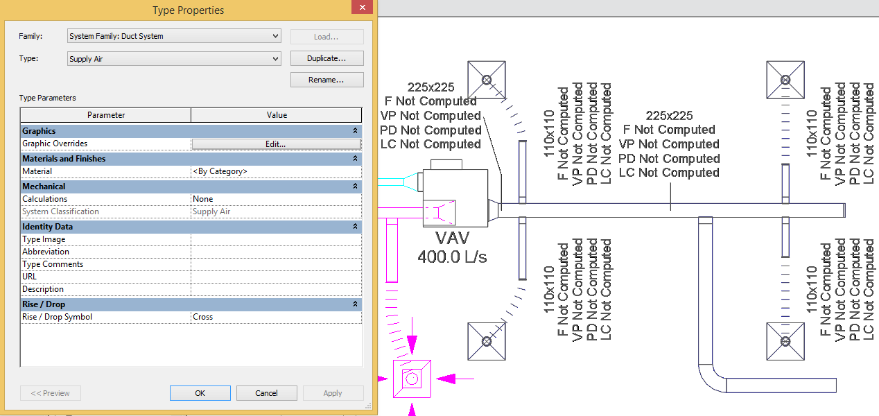
We also have the ability to control what calculations will take place per duct system. When entering the type properties of a duct system, one will be able to choose between:
  •       All: Both Flow and Pressure Drop calculations will take place and ducting can be sized automatically
  •       Flow only – Only Flow calculations will take place and ducting can be sized automatically
  •       None – No Flow or Pressure Drop calculations will take place and ducting can be sized automatically
  •       Performance – No Flow or Pressure Drop calculations will take place and ducting cannot be sized automatically

Performance is a new addition to the available duct systems calculation property.  My best bet would be that this was added for large projects where considerable lag is experienced when Revit is running its calculations in the background. This will be a good option to choose when ducting is being modelled. Flow and Pressure Drop calculations can then be activated at a later stage for auto-sizing purposes. Thus: When modelling - Performance, and when designing/validating – All.

Calculations: All – Both Flow and Pressure Drop calculations will take place and ducting can be sized automatically


Flow only – Only Flow calculations will take place and ducting can be sized automatically

None – No Flow or Pressure Drop calculations will take place and ducting can be sized automatically

Performance – No Flow or Pressure Drop calculations will take place and ducting cannot be sized automatically

Monday 23 February 2015

Stair Landing Opening

A recent query one of my clients had, was on how to add an opening to a staircase landing. The default Revit opening commands cannot cut through a staircase, whether it is a run or a landing. An in-place void also does not cut through a stair (I avoid in-place families like the plague anyway).

As can be seen from the images below, we need incorporate the tree into our staircase design. The green circle represents the opening we need to add to our stair.

Edit the stair and modify the landing boundary to incorporate half of the opening required.

Mirror the landing on the horizontal boundary line to create a complete opening through which the tree can pass.

Delete all unnecessary stringers and railings. You will notice that we still see lines indicating that this stair is actually composed out of two landings. Using the linework tool, we can override unnecessary lines using the Invisible Line linestyle.

The final result will look as per the image below

Wednesday 18 February 2015

Interactive Panoramic Cloud Render

Potatoe-Potato, Tomatoe-Tomato, Doughnut-Donut.

Irrespective of what the correct grammar is, this entry will focus on one of my testing projects: The Do-Nut-Stop. One building has panels that are closed, and the other has panels that are open at 10 degree intervals.


Still internal render:

The main focus will be on one of the new features when rendering through the cloud: Interactive Panoramic Render. To render in the cloud, browse to the View Tab, Graphics Panel, and start the Render in Cloud command.

From the view selection window, change your Output Type to Interactive Panorama.

Once the views have rendered, you will be able to download and save the result either as an Image Strip, or as a HTML file. 

The images below is of a HTML file in which you can pan around the view origin to see a 360 degree representation from that point. 

Building A_Exterior_Closed Panels


Building B_Interior_Open Repeating Panels

Tuesday 17 February 2015

Auto-Sizing Air Terminal

Self-sizing, or Auto-sizing diffusers are a very valuable item in a MEP engineer's Revit arsenal. Why do you constantly need to refer to the air terminal catalogues for sizing purposes, when you can build the specifications into a Revit family?


This blog entry will focus on how to create a self-sizing / auto-sizing diffuser, which will also adjust the throw radius as the airflow and pressure drop increases or decreases. This diffuser example will use the Rickard CCD3 Performance Data. Supply air diffusers have been placed  according to a thumb-suck 2.5m radius throw.

To control the neck size, according to the flow parameters, I have added the following formula to the driving instance parameter: Duct Radius: if(Flow < 117 L/s, 150 mm, if(Flow < 184 L/s, 200 mm, (if(Flow < 261 L/s, 250 mm, if(Flow < 332 L/s, 300 mm, if(Flow < 461 L/s, 350 mm, 350 mm))))))


To control the diffuser throw radius, I have added the following formula: if(Flow < 117 L/s, 1750 mm, if(Flow < 184 L/s, 1950 mm, if(Flow < 261 L/s, 2100 mm, if(Flow < 332 L/s, 2300 mm, if(Flow < 461 L/s, 2500 mm, 2500 mm)))))
Thus, whatever the flow would be per diffuser, the neck size would automatically adjust accordingly, as well as the throw radius.

Easy, isn't it?

Monday 16 February 2015

Poll: RSA - Revit Cape Town User Group

I have been playing around with the idea of establishing a Revit User Group here in Cape Town. The primary purpose of this User Group will be to learn (No, we don't know everything), as well as to network with different industry professionals. 

I have created a Poll underneath the About Me info on the top right of the blog. Should enough interest exist for such an initiative, we can start chatting about dates, times, duration and the amount of wine that will be required.

Please spread the word about this poll so that it can become a standing event in the Mother City!

     UPDATE_2015.02.24_5 Votes
           I am not sure if it would be viable to hold a UG for 5 users? Let's see if we can have at least 10 attending users for the first session

Count me in!
  4 (80%)
Sounds good
  1 (20%)
Meh...
  0 (0%)
I'm too lazy to learn
  0 (0%)


     UPDATE_2015.02.20_5 Votes

Count me in!
  4 (80%)
Sounds good
  1 (20%)
Meh...
  0 (0%)
I'm too lazy to learn
  0 (0%)

Wednesday 11 February 2015

Phasing: Roof Demolition

Revit’s built-in Phasing capabilities are quite easy to understand, especially if one remembers that phasing works according to a timeline. Whatever happened in the past, is existing, and whatever will happen in the future, will be a new construction. The example we will use will be of an existing building with the addition of a new entrance area.

The building already exists, so we need to select all geometry and change its phase to Existing


I have made a few changes to the graphic override filters for the projects phases, to make the New Construction phase’s Cut- and Projection lines thicker, and the Existing phase’s line colour lighter. The Demolished phase has also been changed to Red Dashed lines with a light red solid fill.  Typically one would have a separate view for the Existing phase and another separate view for the new construction phase, but for the purpose of this exercise, I will change the current view’s phase to new construction. When the new entrance area walls are drawn, it will adopt the phase of the current view (Thus, new construction).

Demolishing a portion of roof is quite different to the methodology of demolishing any other element in Revit. We will need an existing roof structure, a new roof structure, as well as an exact match to the portion of roof to be demolished. We will go through the latter steps below.

When we create the new entrance area roof, we will need to join the two roofs together via the Join/Unjoin Roof command, found in the Modify tab, Geometry Panel, Join/Unjoin Roof command.


In order for this roof demolition method to work correctly, as well as be graphically represented on plan in the correct way, we need to edit the existing roof’s boundary, to exclude the roof portion that should be demolished.

The roof portion that needs to be demolished should be drawn as a separate roof. Once the roof has been created, the Phase Created parameter must be set to Existing, and the Phase Demolished, to New Construction.


The images below shows what one will see in a wireframe mode.

We will demolish the section of wall in the new entrance area by using the Split Elements command, and setting the demolished wall’s Phase Demolished to New Construction.


The images below will indicate what building elements will be seen at which Phase Filter Status

Monday 9 February 2015

IFC Import and Export Setup

This blog entry will introduce you to the IFC Linking and Export capability we find in Revit. The dataset we will use will be the: RAC_Advanced_Sample_Project, found in the following location on your local hard drive: C:\Program Files\Autodesk\Revit 2015\Samples

To export to an IFC format, browse to the Application menu, Export, IFC.
 

Within the Export IFC command, you will be able to specify four export properties:
  • Export the current view only
  •  Should walls and columns be split by storey or not
  • Should base quantities be exported or not
  • Should Space Boundaries be included in the export


 When the IFC file is linked into a new project, you will notice a few oddities in the file. First of all, the topography in the OFC file shows primary contours, secondary contours, as well as the triangulation edges.

Secondly, some walls and furniture elements are missing in plan view, and there seems to be a disconnect between the curtain wall door and curtain wall to the bottom left of the image.

Let’s investigate why this happened, and how we can remedy it from happening again in future. Firstly, let us look at the additional data files that are created when the IFC Export command is executed. We will find an export log file and export shared parameters file. 


The export log file will show errors that happened during the export process, the Revit entities that were processed, as well as the IFC elements that were created during the export.


The export shared parameters file will provide a list of shared parameters that were created, the kind of shared parameters (text, number, integer, etc.), its visibility setting (1=ON, 0=OFF), and whether the shared parameter is modifiable by a user (1=YES, 0=NO)

Now, during the export process, Revit will use a pre-defined text file to understand which IFC Class Name, and IFC Type to assign to which Revit categories. The IFC Options command can be accessed from the Application Menu, Export, Options icon, IFC Options.


You will be able to access the exportlayers-ifc-IAI.txt file through Revit’s interface. Changes can be made either from within Revit to the IFC Options, or by accessing the text file by browsing to the C:\ProgramDATA\Autodesk\RVT 2015\ folder location.
 

One can create or modify your own IFC Export Layers text file, but make sure that you comply to the layer requirements as set out in the text file (Indicated by a hashtag)

 Similarly, one will also have IFC Import options. These options can be accessed from the Application Menu, Open, IFC Options.

You will enter your Import IFC Options command, where you can start assigning Revit categories and sub-categories to the various IFC Class Names, and IFC Class Types.


Both the Import and Export Options for IFC file formats can be saved to an external file, and loaded into an existing project (If it has not yet been added to the existing company template/s).