"Anything that is worth teaching can be presented in many different ways. These multiple ways can make use of our multiple intelligences." - Howard Gardner
Imagine working on a project where there are multiple buildings/rooms/spaces which looks exactly the same, but in different locations, elevations or orientations. Many think that each one of those buildings/rooms/spaces must be handled as separate project files, which would then be linked into the Master Project file (Typically the Shared Levels and Grids Project, containing the topography)
However: There is an easier way of doing this
In this example, two buildings were created, each in their own project file. Multiple instances of these buildings were placed in different locations, at different elevations and orientations within a Federated Project file. By entering the Shared Site functionality of a specific link, notice that one can record the position of this linked file's INSTANCE. This is a very important concept to remember. Even though we are working with one file, changing this setting will only affect the selected instance/s.
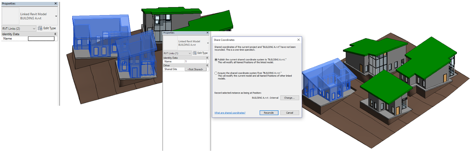
Notice that we can create multiple positions of the same linked file, thus being able to place multiple instances of the same building in our project, and record those unique positions.


Should anything change within the linked files, it will update automatically, retaining the position, elevation and orientation.

Even your schedules, provided that you have entered the correct non-graphical information into your linked files and linked instances, will show the correct information.

Seeing that it is Friday, how about a bit of philosophy?
Irrespective of whether you agree with Howard Gardner's theory at the start of this blog entry or not (Intelligences versus Aptitude versus Personality Traits), I do believe that Education and Training needs to adapt to the ever changing times, industries, atmospheres and technologies.
People's behaviours and perceptions also needs to drastically change. Don't get me wrong, this is not a rant. However, I came across a very thought provoking Ted Ed talk by the former host of Dirty Jobs, Mike Rowe: Learning From Dirty Jobs.
Yes Mike, I got a lot of things wrong too


