Search This Blog

Friday 28 April 2017

100 000 Views - A new Revit Recess milestone

It seems very apt to start this blog entry off with a huge THANK YOU! Revit Recess has just reached the 100 000 view milestone! This could not have been possible without you.


Statistically speaking, 46% of all readers are based in the United States, followed by Russia, South Africa, United Kingdom, Australia and Canada if we look at the Top 6 countries. Chrome is still the internet browser of choice (66%) with Internet Explorer and Firefox at 15% and 11% respectively. 

The Top 5 most popular posts are:
1. Revit Planting RPC Source File
2. Revit LED Striplights
3. Revit LED Striplight Creation Tutorial
4. Fun with 5 Custom Staircase Designs
5. Revit 2016 Render Engine Comparison

So, what is next for Revit Recess? What would you like to see or read about? Would you be interested in a Youtube channel? Livestreaming through Twitch? Let me know in the comments


Thursday 13 April 2017

Euclidian Egg Construction - Happy Easter!

Euclid (300BCE), sometimes called Euclid of Alexandria to distinguish him from Euclides of Megara, was a Greek mathematician, often referred to as the "father of geometry". He was active in Alexandria during the reign of Ptolemy I (323–283 BCE). His Elements is one of the most influential works in the history of mathematics, serving as the main textbook for teaching mathematics (especially geometry) from the time of its publication until the late 19th or early 20th century. In the Elements, Euclid deduced the principles of what is now called Euclidean geometry from a small set of axioms. Euclid also wrote works on perspective, conic sections, spherical geometry, number theory, and rigor. Source: Wikipedia

This Revit Recess entry will explain the steps required to create a Euclidian Egg in Revit. I have used Takaya Iwamoto's Draw a Real Chicken Egg as reference material.

I tend to get extremely confused when instructions state, for example, that the "centrepoint of circle A should intersect with point P1, while intersecting with circle H1's centrepoint". I tend to think in pictures, so instead you will find pictorial instructions on the required steps below.

Step 1:

Step 2:

Step 3:

Step 4:

Step 5:

Step 6:

Step 7:

Step 8:

Step 9:

Step 10:

Have a safe and festive Holy Week and a joyful Easter Sunday, folks!

Monday 10 April 2017

Alternative Visualization Methods - Part 2

Following the popular Revit Recess blog entry: Alternative Visualization Methods, I have decided to show two additonal ways of creating funky visualizations in Revit.

I am a big lurker on the DevientArt website, and came across the following image.

And I thought to myself, how on earth can you create a dusty lens effect in Revit? The first portion of this entry will demonstrate how. However, before I even start. A little wish: Please allow us to symmetrically crop a camera view, Autodesk? We cannot add reference planes to a camera view. We cannot pick a face in a camera view to add model lines. And we cannot add detail lines in a camera view. Trainsmash? Not at all. But it would be nice, though...

None the less, after using the origional image as a baseline and creating the theatre in 3D, I sourced this dusty camera lens image from the internet. 

The challenge was to get this image superimposed on the camera view for a render. And it was not as difficult as one would imagine. Remember: There is always a workaround. We just have to find it! Within the camera view, I created a 100% transparent wall and added the dusty lens image as a decal to the wall face. The decal had an approximate transparency value of 80%, with a brightness bumped up to 15%.

The end result after changing the Saturation value to grey? Pretty awesome!

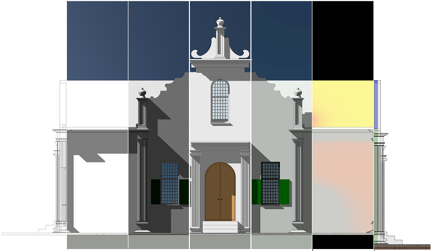
The next alternative visualization method is a slight deviation from the entry shown at the start of the blog entry. This image progressively morphes from a Wireframe to Hidden Line, to Shaded, Consistent Colours, Realistic to Lighting Analysis, and finally Structural Analysis Visual Styles.

The first step was to create dedicated views and renders of each visual style.

The next few steps was to create dedicated views with dedicated scope boxes for each visual style. The last few steps of "stitching" the images together can be found in this blog entry.

This was a fun one! Hope you enjoyed it too!

Thursday 6 April 2017

Model Text versus Complex Fonts

"Model text is a work plane-based 3D element that you can use for signs or lettering on a building or wall." - Autodesk Knowledge Network
This Revit Recess Entry will demonstrate what happens with complex fonts once we drastically decrease the size of a Model Text font.

Basic or simple fonts such as Arial Narrow rarely cause problems when decreasing the font size, as per the image below:

However, when more complex fonts are used, like Mistral, one can clearly see a regression in the font appearance at sizes of approximately 50mm and below. The question is: Why?

When we look at the model text from a 3D view, one can clearly see many different faces that is required to create the curvature of each letter. 

The smaller the text, the smaller these faces will become. Remember that Revit has a minimum element size of 0.8mm. In other words, if a face becomes thinner than 0.8mm, Revit will not be able to create it.