Let's play and see how far we can push Revit, shall we?
Friday, 30 January 2015
Identity Crisis
Even though I absolutely love the "Revit-Alizing" name, there were a few snags on Google searches. So let's see the new name change to Revit Recess as an identity crisis, rather than a midlife crisis ;)
Thursday, 29 January 2015
BIM Manager Roles and Responsibilities
An in-house BIM Manager is one of the most important and valuable business decisions one can make at any stage of a company's Revit adoption/implementation period. They are specialists in their fields, have expert knowledge of a wide range of software solutions, and most of all, vast industry experience.
It so often happens that a company provides the BIM Manager role to one of their staff members, assuming that their company will now instantly experience an increase in performance, have less coordination issues, and meet unrealistic deadlines. Unfortunately, companies often expect the staff-based BIM Manager to also actively work on a project.
There are 24 hours in a day. In our industry, we need at least 6 hours of sleep. At least an hour or two of rest. Two hours of travelling to and from work. This leaves the average staff member with 14 theoretical hours in which to be productive. Studies (and common sense) have shown that a 9 hour working day is "optimal" for the average worker.
Will it really be productive and realistic to expect one staff member to fit two job descriptions into a 9 hour day (or 14 hours some)?
The benefit of contracting a BIM Manager to be part of your team is that they do not get pulled into projects. Yes, a big part of their responsibilities are to coordinate all drawings etc., but they typically do not assist with designing a building, nor do the typical "CAD Monkey" work. Another huge benefit is that they are impartial to office politics (Every office has office politics). Thus they can focus on what they do best: Managing your projects, ensuring that best practices are applied, and coordinating hundreds of drawings, to name but a few.
The responsibilities of a BIM Manager does not end with the few points I have listed above.
A very good guideline to the rules and responsibilities of a BIM Manager can be found on www.bimmanager.com
Monday, 19 January 2015
Revit Hardware Requirements
I
often receive requests for information about the true (Read: Realistic)
hardware requirements for running Revit on a Windows operating system. Autodesk
does provide a detailed explanation of hardware requirements for not only
Minimum and Balanced requirements, but also for Large and Complex models.
Minimum Entry-Level Configuration
- Windows® 7 32-bit Enterprise, Ultimate, Professional, or Home Premium edition operating system
- Single- or multi-core Intel® Pentium®, Intel® Xeon®, or i-Series processor or AMD equivalent with SSE2 technology (highest affordable CPU speed rating recommended)
- Multiple cores for many tasks, up to 16 cores for near-photorealistic rendering operations
- 4 GB RAM (Usually sufficient for a typical editing session for a single model up to approximately 100 MB on disk. This estimate is based on internal testing and customer reports. Individual models will vary in their use of computer resources and performance characteristics.)
- Models created in previous versions of Revit products may require more available memory for the one-time upgrade process
- Virtual Memory Switch (3GB SWITCH) not recommended. Revit software and system stability can be affected by memory conflicts with video drivers when the /3GB switch is active.
- 5 GB free disk space
- 1,280 x 1,024 monitor with true colour
- Display adapter capable of 24-bit colour for basic graphics, 256 MB DirectX® 11-capable graphics card with Shader Model 3 as recommended by Autodesk
- Microsoft® Internet Explorer® 7 (or later)
- MS-Mouse or 3Dconnexion®-compliant device
- Download or installation from DVD9 or USB key
- Internet connectivity for license registration and prerequisite component download
Value: Balanced Performance
- Windows® 8 64-bit Enterprise or Professional edition, or Windows 7 64-bit Enterprise, Ultimate, Professional, or Home Premium edition operating system
- Multicore Xeon or i-Series processor or AMD equivalent with SSE2 technology (highest affordable CPU speed rating recommended)
- Multiple cores for many tasks, up to 16 cores for near-photorealistic rendering operations
- 8 GB RAM (Usually sufficient for a typical editing session for a single model up to approximately 300 MB on disk. This estimate is based on internal testing and customer reports. Individual models will vary in their use of computer resources and performance characteristics.)
- Models created in previous versions of Revit software products may require more available memory for the one-time upgrade process
- 5 GB free disk space
- 1,680 x 1,050 monitor with true colour
- DirectX 11 capable graphics card with Shader Model 3 as recommended by Autodesk
- Internet Explorer 7 (or later)
- MS-Mouse or 3Dconnexion-compliant device
- Download or installation from DVD9 or USB key
- Internet connectivity for license registration and prerequisite component download
Performance: Large, Complex Models
- Windows 8 64-bit Enterprise or Professional edition, or Windows 7 64-bit Enterprise, Ultimate, Professional, or Home Premium edition
- Multicore Xeon or i-Series processor or AMD equivalent with SSE2 technology (highest affordable CPU speed rating recommended)
- Multiple cores for many tasks, up to 16 cores for near-photorealistic rendering operations
- 16 GB RAM (Usually sufficient for a typical editing session for a single model up to approximately 700 MB on disk. This estimate is based on internal testing and customer reports. Individual models will vary in their use of computer resources and performance characteristics.)
- Models created in previous versions of Revit software products may require more available memory for the one-time upgrade process
- 5 GB free disk space; 10,000+ RPM for Point Cloud interactions
- 1,920 x 1,200 monitor with true colour
- DirectX 11 capable graphics card with Shader Model 3 as recommended by Autodesk
- Internet Explorer 7 (or later)
- MS-Mouse or 3Dconnexion-compliant device
- Download or installation from DVD9 or USB key
- Internet connectivity for license registration and prerequisite component download
However, what does this mean for you and me? If you are a one-man-band, which computer should you purchase? What if you have a team of 10, or 20 users working on large complex models? Which computer should you purchase then? The answer is not as simple as many people believe. Personally, I believe that the requirements of your computer is directly related to the way one designs and models a project, not only during the conceptual phase, but all the way through construction documentation and as-builts. Looking towards the facilities management level (Which I believe the industry is moving towards at a rapid pace), the more important your decision becomes. One might have a perfect design, but if your modelling practices are sub-standard, then your computer performance will suffer.
If your computer performance suffers, then you will lose time and money, your frustration levels will rise dramatically, and you will revert back to the olden days of using AutoCAD. How do we avoid the latter from happening? It is very simple actually. Similarly to every principle in Revit, think towards the future. Do you want to buy a low-end computer that will suit your immediate needs? What if you get a project that is twice the size of your current projects? Do you really want to struggle with a slow and unresponsive computer close to a deadline?
I believe that to buy cheap, is to buy expensively. I do not want to upgrade my computer every six months to stay up-to-date with the latest technology. Which brings me to my next point: We are professionals. Thus it is expected of us to have the latest technology to do our jobs as accurately and thoroughly as possible. The crux of the matter is to buy at least one level up from the recommended hardware configurations Autodesk recommends.
Yes, it will be more expensive. Yes, your superiors (or you yourself) will complain about the costs. But do you really want to be that person, that company, who has to admit that you cannot collaborate/coordinate/model a project because your hardware is not up-to-scratch? Get the best computers you can possibly afford. And while you are at it, buy another monitor. It is worth its weight in gold.
Wednesday, 14 January 2015
Introduction to Energy and Daylighting Analysis
This entry will
be a short introduction to energy and daylighting analysis in Revit, which is
available to Autodesk subscription members only.
Let’s focus
on the Energy Analysis functionality available in Revit. First of all, one can run an energy analysis
(by making use of the cloud services) for either a conceptual mass design, or for a Revit
building element (i.e. Revit walls, floors, windows, doors etc.) This command can be accessed from the Analyse Tab, Energy Analysis panel.

Once
accessing the Energy Settings, one can change a myriad of energy settings for a
specific project, from the Building Type, to Detailed Model settings, Energy
Model Settings, and Building Energy Services. All of these settings will be
taken into account once the energy simulation is run.

Upon
running the energy simulation, the following results will be emailed to your
registered subscription email address.
1. Building Performance Factors

2. Energy Use Intensity, Life Cycle Energy Use/Cost, Renewable Energy Potential

3. Annual Carbon Emissions

4. Annual Energy Use/Cost

5. Energy Use: Fuel

6. Energy Use: Electricity

7. Potential Energy Savings

8. Monthly Cooling and Heating Loads

9. Monthly Fuel Consumption

10. Monthly Electricity Consumption

11. Monthly Peak Demand

12. Annual Wind Rose (Speed Distribution)

13. Annual Wind Rose (Frequency Distribution)

14. Monthly Wind Roses

15. Monthly Design Data & Annual Temperature Bins

16. Diurnal Weather Averages

17. Humidity

Daylighting analysis (After setting various parameters), which will be accessible after installation of the add-in, will provide you with detailed images complete with lux levels.


Monday, 12 January 2015
Revit Detailing
Welcome
back to the first Revit-Alizing blog entry of 2015, which will discuss
detailing in Revit, focussing on the MEP environment. I hope you have had a
safe and festive season.
We will
follow the steps needed to create 2D Revit families, and adding those families
to what we call a Source File. A Source File can contain all details for a
specific discipline/category, irrespective of what it is. A good example of
System Family Source files can be found in the following Revit OOTB location: C:\ProgramData\Autodesk\RVT
2015\Libraries\UK\System Families.

To create a
dedicated MEP detailing Source File, we need to start a new project. We will
not need any views except for Drafting and Legend views in this source file, so
we can delete all unneeded views from this project.

Create a
new drafting view from the View Tab, Create Panel, Drafting View icon. Provide
a name for the detail you want to create.


It is
always a good idea to organise the drafting view into the applicable discipline
and sub-discipline upon creation, to ensure that no time is wasted
re-organising all the views at a later stage.
In the
image below, we can see that it is indeed possible to simply import a legacy
CAD file into Revit. However, note the following:1. Some valve hatches do not show
2. Certain line patterns are not the same in Revit as it is in AutoCAD
3. Simply importing any CAD drawing, whether it is a floor plan, or details, or anything else, adds a LOT of weight to your Revit file. Avoid importing any CAD file at all costs.

The Revit Best Practice method for detailing is to create separate Revit families for all details, such as a separate Revit family for a butterfly valve, a separate Revit family for a motorised control damper, etc. etc. Not only will this greatly reduce the size of your Revit project, but it will also enable you to use these details in a 3D family as well (In other words, on plan one can see a symbol, and in 3D the actual Valve geometry). Import the required detail into a Revit Detail Item family, and position a valve at the intersection of reference planes. The location of the valve in relation to the 4 quadrants of the reference planes will determine the basepoint of the family upon insertion into the project/source file.

In a Detail Item family, text will not propagate through to the project. One has the option of now either creating the entire symbol family as a Generic Annotation rather than a Detail Item, or one can create the required text as a generic annotation and nest it into the Detail Item family. A family created based on the Generic Annotation family template will stay the size it was drawn at any scale (i.e. valve diagonal measurement as 5mm will be 5mm on paper at a scale of 1:1 and at a scale of 1:5000). A family created based on the Detail Item family template will scale up/down based on the scale of the view (i.e. valve diagonal measurement of 5mm at a scale of 1:100 will be 500mm at a scale of 1:1).

Create
separate families for all of the required items (One can look at this as
creating separate blocks for each item in the old AutoCAD language) I prefer
structure in my Revit libraries, This is why I have a specific naming
convention as can be seen from the image below.

All that is
left now, is to recreate the AutoCAD detail in Revit, using the pre-created
Detail Item families and the required lines and text.

Note
however the one drawback to creating details in the drafting view: Only one
drafting view detail can be placed on a sheet. This is due to the fact that one
can reference a section, callout, elevation etc. to a specific drafting view
(detail). It would be aces in my book if one can place one drafting view on
multiple sheets and choose the reference method manually. Now what can we do to
overcome this obstacle?

It is actually very simple: Create a legend view and follow the same steps as listed above.

Legend views can be added to multiple sheets. One of the two drawbacks to legend views are that they will not automatically be referenced when placed on a sheet.

The more legend views and details you create, the more elaborate and concise your Source File will become.

The accepted method of adding views from one project to another is via the Insert Tab, Import Panel, Insert from File Icon, Insert Views from File command. However, one can only insert Drafting Views, not Legend views.

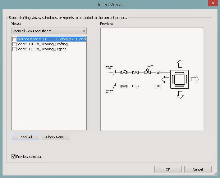
Workaround please? <Ctrl + C>, <Ctrl + V>. In other words, the old copy, paste. Copy the detail from the source file, paste it into the project. Copy the legend view name from the source file, paste into the project.

Subscribe to:
Posts (Atom)