Search This Blog

Monday 29 June 2015

Placing Doors and Windows Independently from Level

We all know that, when in a plan view and starting a command, by pressing the Shift keyboard button we enable the Ortho constraint.

In a 3D view however, when placing a door or window, these elements will automatically be placed on the levels specified in your project (Where after one can specify the correct head/sill heights). When pressing the Shift button though, you will be able to place these doors and windows independently from your level.

Although this might not be a game changer, it is a nice to know.


Thursday 25 June 2015

Introduction to Autodesk Memento (Beta)

"Autodesk Memento is an end-to-end solution for converting any captured reality input (photo or scans) into high definition 3D meshes that can be cleaned up, fixed, and optiomized for the Web, mobile or 3D printing/fabbing. 

Memento is part of Autodesk's Reality Computing portfolio and is a great companion to ReCap"

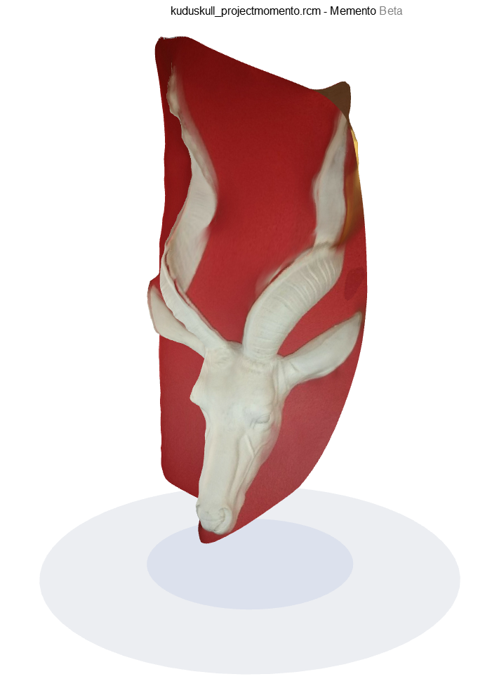
I recently tested Autodesk Memento Beta for the first time, using a plastic Kudu skull mounted in a restaurant as a sample. The Kudu skull was mounted quite high above the floor, so taking the required number of pictures at the required angles was a bit of a challenge. None the less, I managed to take 26 OK-ish photos. (Tip: The more photos you take, the better!)  

After Autodesk Momento stitched the photos together, the end result looked as per the image below. Due to the fact that I have not taken enough photos at different angles of the left horn, the stitching is sub-standard at that area. 

There are quite a few modifaction settings one can now access in Autodesk Memento to fix the 3D model. We will go through the options in the rest of the blog entry.

The first property we can change:
1. Model Settings
   - Set Model Upright
   - Set Origin And Coordinate System
   - Set Scale And Units

2. Edit
    - Slice and Fill
    - Surface Tools
    - Delete Selected Mesh
    - Fill Holes in Smooth Mode
    - Bridge Large Gaps in Mesh
    - Extrude Selection
    - Smart Selection Based on Texture and/or Geometry

3. Retropologize
    - Re-triangulate Selected Mesh
    - Subdivide Selected Mesh
    - Decimate Model

4. Analyze
    - Detect and Fix Mesh Issues
    - Measure Distance
    - Mesh Report
    - Analyze the Diference Between Two Models

 5. 3D Print

6. Export Model
    - Export 3D Model
    - Export Video
    - Export Image

* A future entry will show the end-result of editing that took place in Autodesk Memento, as well as Autodesk Recap *

Friday 19 June 2015

Revit LED Striplights

This blog entry will aim to explain two main workaround methods for the creation of LED Strip Lights in Revit. The application of these methods are applicable to both the Architectural Discipline, as well as the Electrical Discipline. As with everything in life, there are pro's and con's to both methods, which will be explained in this entry. 

A very simple room was created with a feature bulkhead ceiling. The ceiling contains straight edges, as well as a curve. 

Method 1: LED Strip Lights as Lighting Fixture family nested into Generic Line-Based family

The image below is the rendered result of a strip light family created as a Generic Line-Based family, in which a lighting fixture was nested. The rendered result looks a bit too "artificial" for me, personally. However, one can nest electrical connectors in this line-based family, which can be used to create circuits from. 

One cannot natively create a curve in Revit using a line-based family. One can however represent a circle using the Inscribed Polygon's and Circumscribed Polygon's Draw command. The maximum amount of sides one can specify in 36. Thus, the circle will be broken into 36 separate lines.  

The settings used for the line-based family render includes the following:
1. Render Engine: NVIDIA Mental Ray
    Setting: High
    Resolution: Printer at 300 DPI
2. Artificial Lights: 56 (This includes the recessed can downlighters)
3. Physical Memory Used: 4.52 GIG
4. Laptop CPU temperature: CPU fan on decreased the temperature with approximately 10 degrees Celcius
5. Laptop CPU Usage: 100%
6. Render Duration: The render was complete after 3 Hours and 44 Minutes
7. I do need to mention that I was rendering the two different Strip Light creation methods simultaneously, just to see how far I could push my laptop.This has added to the total render time.

Option 2: LED Strip Lights Railing family

The image below is the rendered result of a strip light family created as a Railing family. I quite prefer the railing strip light result, as the light diffusion looks much "softer" and "natural", when compared to the line-based family's result. The drawback to using this method is that one cannot nest electrical connectors in the baluster family (Used for the spacing of each strip light segment)

The strip light railing consists out of a rail profile for the LED tube and a separate family for the light source. The light source family was nested into a baluster family. All of these components will be used in the project environment, as a railing is a system family (i.e. created in the project environment).

The baluster family and rail profile was used within a Railing family. The spacing of the balusters took quite a lot of time before I was satisfied with the result. 

The settings used for the railing family render includes the following:
1. Render Engine: NVIDIA Mental Ray
    Setting: High
    Resolution: Printer at 300 DPI
2. Artificial Lights: 203 (This includes the recessed can downlighters)
3. Physical Memory Used: 4.63 GIG
4. Laptop CPU temperature: CPU fan on decreased the temperature with approximately 10 degrees Celcius
5. Laptop CPU Usage: 100%
6. Render Duration: The render was complete after 8 Hours and 53 Minutes (Due to the amount of light sources nested in the baluster family, that had to be processed))
7. I do need to mention that I was rendering the two different Strip Light creation methods simultaneously, just to see how far I could push my laptop. This has added to the total render time.

In a nutshell, below is a simple comparison between the two methods in a table format. A grading of 1 to 5 was used, with 5 being the best and 1 being the worst:

Thursday 18 June 2015

Revit Flower Power

Flower power was a slogan used during the late 1960s and early 1970s as a symbol of passive resistance and non-violence ideology. It is rooted in the opposition movement to the Vietnam War. The expression was coined by the American beat poet Allen Ginsberg in 1965 as a means to transform war protests into peaceful affirmative spectacles. Hippies embraced the symbolism by dressing in clothing with embroidered flowers and vibrant colors, wearing flowers in their hair, and distributing flowers to the public, becoming known as flower children. The term later became generalized as a modern reference to the hippie movement and the so-called counterculture of drugs, psychedelic music, psychedelic art and social permissiveness.
Blue Lotus (Nymphaea caerulea)


Gazania


Thursday 11 June 2015

Electrical Circuit Naming Conventions

The need often arise where the default circuit naming convention in Revit needs to be modified or changed to suit company standards. 

When selecting a panel, in the Electrical - Circuiting area of the Properties Panel, a property called Circuit Naming exists. By default, no circuit naming is applied to your panels. The circuits will thus be named numerically.

When changing the Circuit Naming to Panel Name, as can be seen from the panel schedule below, the panel name will now be added as a prefix to the circuit name.

With Circuit Naming set to Prefix, you will be able to add both a Circuit Prefix, as well as Circuit Prefix Separator.  

A Standard Circuit Naming will show only the circuit numbers

Circuit Naming by Phase adds the default Phase A, Phase B, and Phase C prefix to circuits.

Should the circuit phase prefixes need to change, it can be accessed by changing the General Electrical Settings for the project and/or template.

Tuesday 9 June 2015

Revit 2016 Duct Loss Method Settings

Revit 2016 now provides us with the ability to specify the Loss Method Coefficient for Duct Fittings graphically from the ASHRAE table.

When selecting a duct fitting, the Loss Method Settings can be accessed from the properties panel, Mechanical Area


One will now be able to specify a different coefficient from all applicable fitting types.

When enabling the View All checkbox, one will see all coefficients for the elbows, but those not applicable to the selected duct fitting, will be greyed out. 

Monday 8 June 2015

Revit 2016 Render Engine Comparison

NVIDIA Mental Ray or Autodesk Raytracer? That is the question. I believe that both render engines have their advantages and disadvantages. 

The first render engine comparison is of an exterior day render. The NVIDIA Mental Ray image is on the left, while the Autodesk Raytracer image is on the right. Even though these two renders were created using the same quality settings, sun settings etc., one can clearly see that the Autodesk Raytracer engine saturates colours far more than the NVIDIA Mental Ray engine.

When comparing an internal night render, one can see that the NVIDIA Mental Ray engine is far more "realistic" than the Autodesk Raytracer engine. Pay attention to the floor lamp on the left. No electrical, nor photometric properties were changed between the two renders, yet something is "off" about the lamp lighting. (It might have been a mistake on my side)

If you do not have access to a dedicated rendering/visualization program and you can only render from within Revit, if your renders do not look "perfect", there is no need to start moaning about the "limitations" of the program. You have 5 main options to choose from:
1. Choose which render engine will give you the best result: NVIDIA Mental Ray, or Autodesk Raytracer.
2. If one of the above options do not give you the results you want, how about rendering through the Cloud?
3. If neither one of the above options work for you, start post processing the image inside of Revit. Change the Highlights, Saturation, Mid Tones, etc. to make your image as close to perfect as can be.
4. You always have the option to export your Revit model to an external software program, such as Autodesk 3ds Max, Autodesk Showcase, Autodesk Navisworks, even Autodesk AutoCAD. From within these programs, you will be able to tweak your renders even further
5. Use post-processing software such as Adobe Photoshop.

Make due with what you have. Make what you have work for you.

Thursday 4 June 2015

How Revit Calculates Areas

Determining how Revit calculates room areas might not be a huge game changer for you, but it still remains interesting to see how it happens. The example below indicates 3 rooms of varying shapes.

We can export these rooms as a report, which will provide us with the triangulation method used to calculate the room areas. This command can be accessed by navigating to the Application Menu>Export>Reports>Room/Area Report.


The report will include both pictures, as well as a HTML file indicating the triangulation methods used. In the HTML report, Revit will also provide the individual area values, the Gross Area, as well as the total Window Area in the view.


Tuesday 2 June 2015

Stunning Revit Render by Anh Meo

I firmly believe in giving credit where credit is due.

So here goes: Anh Meo recently uploaded a Revit render to the Autodesk Rendering Gallery website, and what a stunner it is! 

Revit 2016 Revisions

Revit 2016 saw some changes being made to the Sheet Issues/Revisions command. We now have access to both Numeric, as well as Alphanumeric revision numbering options

We can change the revision Sequence starting number to rather start at 0 instead of the default 1 (Yay!) For both Numeric and Alphanumeric numbering options, we can now add Suffixes and Prefixes. However, do not jump for joy yet... Adding Prefixes and/or suffixes to your revisions will affect ALL revisions. This is a global setting.

The example below is of a revision numbering with a prefix of "A"

Removing the prefix will affect all revisions, as stated before. 

You will have to make a choice: Do you want all of your revisions to have a prefix/suffix? Or would you rather keep to the 2015 format of no prefix/suffix revision capability. I will leave the choice up to you.

Monday 1 June 2015

Revit Repeaters

Revit was primarily designed to service BIM (Building Information Modeling). However, do not get stuck thinking that Revit only fits into the BIM space. Revit can be used for a lot of other purposes as well, as can be seen from the images below. 

Virusses, micro bacteria, nearly anything can be created in Revit. We just need to find the workaround. The workaround to create these examples was to use the Revit Repeater command. 

The first example is of the HIV Virus.


 Example 2 is of a DNA strand.


The last example was a bit of a challenge: Microbe Bacteria. Creating the bacteria was quite easy, but getting the correct material representation was a tad difficult. Even though it would have been easier in 3ds Max, remember that this blog aims to keep to the default Revit functionality. I believe the result would be good enough to get the message across.