Search This Blog

Friday 24 March 2017

Dimension Line Snap Distance

Dimension Line Snap Distances are very usefull tools in our Revit arsenal. Afterall, who enjoys a drawing that has dimension lines all over with unequal distances inbetween them? As Edna Mode says, "It distracts from the now"

The Dimension Line Snap Distance setting can be found in the Type Properties of any dimension. The default snap distance setting is 10mm (Remember that dimensions are annotative objects).

 By changing the snap distance to 15mm, the end result is clear.

Wednesday 15 March 2017

Far Clipping Explained With 3 Simple Images

I am often asked what exactly the Far Clipping property does when using sections and elevations. This entry will explain exactly that, in 3 images. The images were generated from my previous blog post, The Revit Human Skull.

Far Clipping set to "No Clip"

Far Clipping set to "Clip without line"

Far Clipping set to "Clip with line"

Making sense? It sure does to me.

Monday 13 March 2017

Modena Cape Town Partners With DotProduct LLC

More exciting news! Modena Cape Town has partnered with DotProduct LLC!

A huge thank you to Tom Greeves for travelling all the way from the USA to sunny Cape Town to train Modena Cape Town and providing us with first class training. If only he was here for longer! Our 3D scanning event at the Commodore Hotel in Cape Town was well attended and the attendees well satisfied with the live demonstration and Q&A session.

"Scanning is becoming increasingly popular as a means of capturing undocumented data in the field for accurate verification and to gain faster turnaround times to design and complete projects.

Example
How laser scanning would add value from the beginning of a project.

By creating a 3D model of a project as it develops, an accurate analysis can be conducted by comparing and contrasting the as-built structure against the original design. Any deviation from the original design will be obvious from a visual perspective, as well as providing the survey team with the advantage of being able to interrogate the numerical data used to build the 3D model. Any deviation from the original design can be identified within hours, allowing corrections to be made within a working shift. By building a 3D plan of the development, a model can be used by teams of engineers and planners in the office to investigate specific details of the area that was scanned. This will allow them to determine whether structures like conveyors, monorails, pipes, and other services will fit as planned.

The following video is an example of this workflow as it really demonstrates capturing survey data from off-shore and sending the files back to the engineers to redesign. Just one of the many advantages."

"Recap, Revit and AutoCAD are tools ideally suited for incredible modelling to as-built workflows; ranging from green fields to brown fields projects this technology is being used in both the design, as-built and facilities management environments."

A special thank you to my colleague Gary Graham for initiating this partnership, and to my technical colleague Mitchell Parsonage, for demonstrating and narrating the Scan-to-Revit section of the video.

Should you need any sales or technical information on this product, or information on what products and services Modena Cape Town can offer, please do not hesitate to contact us.
Email (For DotProduct Scanners): capesales@modena.co.za (Gary Graham)
Telephone: +27 (0) 21 794 0702

The Revit Human Skull

Inspiration is defined by the Oxford Dictionary as "the process of being mentally stimulated to do or feel something, especially to do something creative".

What inspires you as an architect, an engineer, a visualization expert, or a CAD operator?


Personally I am inspired by others: People like Kelvin Tam, otherwise known as Captainswat for his famous Revit Ironman. Similarly, Marcello Sgamberulli became infamous through his Simply Complex blog entry: The Elephant in the Room, which evolved into The Revit Cow. Zach Kron from Buildz is another favourite of mine, especially for his Parametric Pumpkin Carving competition (Amongst others). Paul Aubin has been another inspiration of mine for the past few years. His Renaissance Revit: Creating Classical Architecture with Modern Software book is well worth purchasing. Andy Milburn from Grevity for fathering Project Soane. And lastly, Jeffrey Pinheiro from The Revit Kid with his books: BIM After Dark, is another great inspiration for me.


I guess that, in a nutshell, I am inspired by people who make the technology they have work FOR them. Kudos to you all and to all the other great authors out there.


This Revit Recess entry will show the steps taken to create a Human Skull in Revit - And as a teaser, look how awesome the rendered result was!


I found a 3D skull family I downloaded months ago from a free CAD website somewhere in my "TBO" folders ("That's To Be Organised" for the non-procrastinators out there). The assembly contained the skull with upper jaw, lower jaw, upper teeth, and lower teeth. These parts were brought into a Mass family, re-scaled and re-positioned to create the Mass family.


Using dedicated levels and sections with named reference planes, I managed to control where I wanted to add reference points (Basically on all triangulation intersections within the views). After these points have been placed, the point element's X-axis position was specified by manipulating the 3D view and moving the XYZ-widget into place.

As can be seen from the image below, I chose to only create point elements on half of the skull, as after I do all of the modelling work, all points and faces can be mirrored across.

Planning, planning and more planning. The time came to plan how I was going "connect the dots", if you will, by placing reference lines.

The most frustrating part of adding reference lines to the point elements was that, based on the view orientation, you might find this annoying error constantly appearing: "Line is slightly off axis and may cause inaccuracies." Where is the remember my choice option??

None the less, it took some tricky orientation changes to model the correct faces based on the point element positions.

Changing the visual style to Wireframe made this portion of the modelling a lot easier, though.

The end result looked like this.

The two halves were then nested into a Master Skull Mass family, and mirrored across.

Aaaand.... here is where I lost track of time. I thought to myself that this skull would look awesome if it was made from gold.
 And then I thought, "while your at it... Why not create a quick render?"

Which evolved into a night render with a studiolight placed inside of the skull itself.


And just for fun (Read OCD), how would a toposurface created from this skull look like? I quite like the result.


Hope you enjoyed reading this one, I certainly did creating it!

Thursday 9 March 2017

Opening Cut: Elevation Transparency Option

It's the little things, like a checkbox we overlook that makes a huge difference. This short Revit Recess entry will show the result of enabling and disabling the Elevation Transparency checkbox in an Opening Family.

Elevation Transparency Off:

Elevation Transparency On:

Tuesday 7 March 2017

Solar Study as Monthly Ranges

I recently came across a question a user posted on the Autodesk Community Forums (ACF), where the user wanted Revit to provide a solar study over a time range - Similar to what we could have done with Ecotect Analysis (The sale of Ecotect Analysis was discontinued in March 2015). I have to admit that I did not use or play around with Ecotect enough when it was available to us - I spent more time researching and using Autodesk Vasari (Another great program which was unfortunately discontinued)

There is a golden rule when it comes to BIM software: "Just because you can, doesn't mean you should". We can definitely achieve a similar solar study result in Revit, but one has to carefully weigh the time spent to the actual benefits. Will the seconds/minutes/hours I spend be billable, or will it be seen as a value added service? I will leave the decision up to you. 

This Revit Recess entry will explain the steps taken to achieve a result as per the origional ACF post.

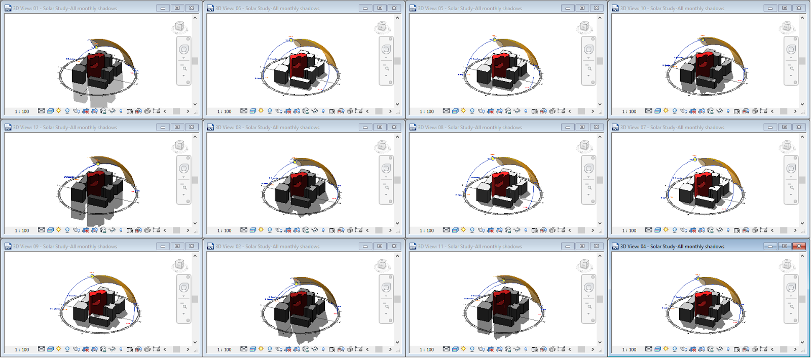
12-off 3D views were created, each with its Sun Path enabled. Each 3D view was set to a different month - starting with January and ending with December. 

A presentation sheet was created and each view placed on the sheet in the same position. (TIP: One can actually snap to the center of views which were placed on a sheet). As we can see from the image below, the sun paths create quite a "busy" view. 

By selecting 11 solar study 3D views and disabling the sun path, one will achieve a much neater representation. 

The end result does look great, though!

Friday 3 March 2017

Why you can't select a viewport on a sheet

There are many one to achieve something in Revit; Alternatively, there are many ways to troubleshoot something going wrong in Revit. This Revit Recess entry will show 5 ways in which we can make a viewport not selectable. There are obvious pro's and con's for this method.

In the examples below, one viewport has been placed on a sheet.

Example 1: The viewport has been selected and Hidden in View > By Element.
Solution 1: Unhide the viewport.


Example 2: The viewport is pinned and the Select Pinned Elements selection option has been unchecked.
Solution 2: Enable the Select Pinned Elements selection option, and unpin the viewport

Example 3: The viewport has been activated
Solution 3: Deactivate the viewport
Example 4: All Annotation Categories have been turned off in the sheet's Visibility Graphics
Solution 4: Make all Annotation Categories visibile

Example 5: The viewport is part of a Selection Set Filter and the filter is turned off in the Visibility Graphics
Solution 5: Turn the Selection Set filter on