Search This Blog

Thursday, 4 August 2016

Autodesk LIVE Design: Create stunning interactive visualizations

"Make your Autodesk Revit model interactive, in one click. Customize navigation points, geo-specific lighting, and render styles. Present to clients, or let them explore on their own, with the free LIVE viewer." - Autodesk

I'm an Architect:
* There's a story behind my vision. I want people to connect with it on an emotional level.
* Let clients feel the space exactly as you envision it.
* Use fast click-to-cloud tools to help make your designs interactive.
* Create and customize expressive visualizations yourself.

I'm a Design Visualization Artist:
* I bring designs to life. I want people to experience what it's like to be inside the space.
* Infuse designs with your unique artistic touch.
* Harness the horsepower of a real-time game engine for interactive visualizations.
* Get ahead of the virtual reality curve by creating immersive client experiences.

If you have confirmed any of the statements above, the Autodesk Live Design program might just be the answer. This Revit Recess post will introduce Autodesk LIVE Design to our readers.

After installing Autodesk LIVE Design, you will find a Go LIVE command under the Add-Ins tab, LIVE Design panel. LIVE Design is a pay-as-you-go subscription service, currently available at a monthly fee of $30US.

As can be seen from the image below, I have installed a trial version of LIVE Design, which allows you to use the program 10 times. After the trial has expired one will need to Subscribe to continue using the program.

I will be using the Architectural Sample Project file's 3D view for this blog entry. Four stages will need to be completed before we can use LIVE Design: We will need to 1. Upload the file to Autodesk's servers, 2. Wait for the file to be processed, 3. The servers will start to prepare the file, and 4. The completed LIVE Design file will be downloaded to your local hard drive (*.lvmd file format).

Once you reach stage 4, you will receive an email from LIVE Design, indicating which view was uploaded, the Job ID, Service version and exactly where the file was downloaded to (By default: C:/Users/<Username>/Documents/Autodesk LIVE 
During the download process, you will notice the LIVE model file size. The Basic Sample Project file LIVE Design file size is 49MB.

After the initial installation of Autodesk LIVE Design took place, an editing program was also installed: Autodesk LIVE Editor. When opening the LIVE model, the LIVE Editor will import the downloaded file, extract the contents and create the visualization scene.

The first time LIVE Design is started, a user interface introduction will appear. All icons and actions will be indicated and explained. You will also be able to take a short (2 minute) video tour.

I have to say that I am quite impressed with the overall quality of the scene.

Changing the date and time of day is extremely simple through the Sun icon.

A function that really stands out for me is the Info command. This command will allow you to select any element in your scene and extract not only the instance properties, but also the type properties of the select element. As has always been the case with Revit, the information we add to the model is king - If you have incorrect or outdated model information, the properties you (Or you client) extracts from LIVE Design will also be incorrect. 

We currently have 3 Visualization styles to choose from. The first style is colour

The second is a partial paper model style - All building elements will be in a paper model mode, while all site elements such as Planting and Topography will remain in colour.

The last style we can access is a partial papermodel mode where all building elements will be in a paper model mode, with all site elements showing in grayscale.

To the right of the LIVE Design window you will find a filmstrip. This strip will contain all of the 3D views that has been created in Revit (Thus, remember to delete all redundant checking views before you prepare your model for presentation). I quite like the fact that one can create additional viewpoints from within LIVE Design - Quite similar to Navisworks and Showcase. Transitioning form one viewpoint to another is very smooth and seamless.

LIVE Design Settings includes Travel Speed, Field of View, and Tap&Go heights. Each of these has thier own settings which can be changed at any time.


To the top right of the LIVE Design window, you will find Help tools - Take notice of the Download Autodesk LIVE Viewer option, which will be discussed at the end of the entry.

To the top left of the LIVE Design window, you can choose to either Publish the scene to Windows, or to an iPad.

I have published the scene to Windows, after which LIVE Design notified me that the presentation is now ready to view.

This is where the importance of the Autodesk LIVE Viewer comes into play: Your client will need to download the Viewer before he/she can access the file. The Viewer is available for download on the Auotdesk App Store. The client will have to create an Account with Autodesk first, before being able to download the Viewer.

NOTE: At this stage (2016.08.04) Autodesk LIVE Design is not available for use in South Africa

Wednesday, 13 July 2016

Save the date: Autodesk University South Africa


As most South African Revit Recess readers will (hopefully) know by now, the local chapter of Autodesk University is being held in Cape Town this year on the 1st of September. This year, AUx is jam-packed with both local and international speakers, Industry specific sessions, South African success stories, free CPD points, an Autodesk Certification voucher, as well as a Design Competition - All of the latter is included in the entrance fee of R650 (R250 for students). I would gladly pay this fee just for the CPD points!


So, let's get to the good stuff: What will we learn, who will be presenting and when will this happen? I took the liberty of highlighting all Modena speakers in the AUx Track Session snippet below.


Do yourself a favour, go to the Autodesk University Extension website and register. Remember to specify where you have heard about the event - If this is the first time, please specify Modena Design Centres.

 Local is lekker!

Tuesday, 5 July 2016

Revit MEP: Design to/versus Fabrication

In Revit 2017, as opposed to the 2016 version, one can now convert existing Revit MEP design elements directly to Fabrication parts. This Revit Recess post will briefly explain the process thereof. As per the image below, we have a simple HVAC system containing Supply Air ducting with spigots, flexible ducting and diffusers. The Return Air system contains spigots, flexible ducting and return air grilles, with the Fresh Air system connected to a common mixing plenum. These elements have been created in Revit.


By selecting all of the elements outlined above, in the Modify/Multi-Select green contextual tab and green Fabrication panel of the Ribbon, we will see a Design to Fabrication command.

The Design to Fabrication command will allow you to convert your current design to MEP Fabrication Parts. This however, needs to be done by first specifying a Fabrication Configuration to use. There are numerous configurations available to us by default, using various Content Packs. Each configuration we choose will contain fittings, valves, equipment, etc. applicable to that specific service.
Once the Configuration Packs have been loaded, we are now able to convert each Revit Service's Design to Fabrication Parts. As you might have noticed, filters were created to colour each Revit Service. Once converted to Fabrication Parts, the converted element colours should reset to default as these elements will no longer apply to, for example, the ducts category, but to the Fabrication Parts category.

In the example below, you will notice various elements which have been converted, and you will also notice that some disconnects and improper element placements exists. This is due to the fact that Revit is a design program, not a fabrication program. The Supply Air transforming piece has been deleted as the Fabrication transformation piece is much longer than the Revit fitting. Similarly, the Return Air spigots now show that the mixing plenum connection is clashing with the unit itself. These are small examples of how the initial design will differ to real-world fabrication and installation scenarios.

Fixing the disconnects and improper placements as explained above is not a difficult process though. We do have the MEP Fabrication Parts tool pallete available in Revit 2017, which will allow us to manually draw and place service parts according to the configurations loaded into our project.  

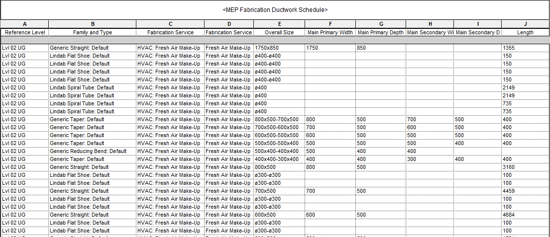
We will notice that our existing duct, duct fittings, and duct accessories schedules will now not show all Revit ducting. This is due to the fact that the Revit ducting, fittings, accessories, etc. have been converetd to another catgeory: Fabrication Ductwork, Fabrication Hangers, Fabrication Pipework, Fabrication Containment, etc. We will need to create seperate schedules for these categories.

There are numerous Fabrication properties we can show within these schedules to create much more elaborate and defined MEP Fabrication Schedules. Just keep in mind that the more parameters (i.e. Columns) we add to the schedule, the wider the schedule will become. If you need to place the schedule on a sheet, keep the information contained in the schedule to the most important fields only.

Monday, 27 June 2016

Floor Plan View Range per Discipline

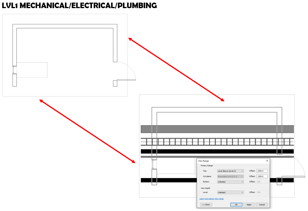
This quick Revit Recess entry will demonstrate the fundamental View Range graphics per Discipline. From the image below we will see a simple room which contains Architectural, Structural, and MEP elements.


Below is the result of changing the Level 1 Floor Plan's View Discipline to Architectural, with the following View Range settings:
     Primary Range:
             Top Range: Level Above with 2300mm Offset
             Cut Plane: 1200mm
             Bottom Range: Unlimited
     View Depth: 
             Level: Unlimited


The result of changing the Level 1 Floor Plan's View Discipline to either Mechanical, Electrical or Plumbing, with the following View Range settings:
     Primary Range:
             Top Range: Level Above with 2300mm Offset
             Cut Plane: 1200mm
             Bottom Range: Unlimited
     View Depth: 
             Level: Unlimited


The result of changing the Level 1 Floor Plan's View Discipline to Structural, with the following View Range settings:
     Primary Range:
             Top Range: Level Above with 2300mm Offset
             Cut Plane: 1200mm
             Bottom Range: Unlimited
     View Depth: 
             Level: Unlimited

And lastly, the result of changing the Level 1 Floor Plan's View Discipline to Coordination, with the following View Range settings:
     Primary Range:
             Top Range: Level Above with 2300mm Offset
             Cut Plane: 1200mm
             Bottom Range: Unlimited
     View Depth: 
             Level: Unlimited


What can we then learn from the examples above? Create a dedicated Coordination Plan view, with the Discipline set to Coordination if any coordination needs to take place. Remember, the Coordination View Discipline is especially effective in a 3D view. Create and make use of filters to ensure turning services on and off is easy to do.

Monday, 13 June 2016

Alternative Visualization Methods

As Revit Recess is a blog investigating the workarounds in Revit, I have thought it would be apt to see what alternative methods one can use to create visualizations. In this entry we will investigate 5 alternative methods to create interesting visualizations in Revit, using only the default tools we get OOTB.

The first visualization example is to create a Mosaic using a combination of duplicated section views, each having their own and unique crop boundary, coupled with a visual style override for each view. The first image was created by duplicating a building section 11 times as a dependent. This allowed me to quickly change each dependent view's crop boundary in its parent view (Why can't we align or snap one crop boundary to another yet?). The challenge here was that if one changes the visual style of one view, all other dependent views' visual styles also change. 

To overcome the latter, all one needs to do is to duplicate each dependent view, as the crop boundary shape and location is retained. The second image shows all those duplicated views added together (Very much like adding Tetris blocks together - the views automatically aligns itself into position). 


The Mosaic visualization above can be taken even further: By creating a thin mosaic mass, with each mosaic section having its own shape and transparent colour, one can effectively add your own "filter" to a scene. Now this is where my ADD kicked in - What does the Refraction properties for materials really do? Below you will find the Refraction results for Air, Water, Alcohol, Quartz, Glass and Diamond. 


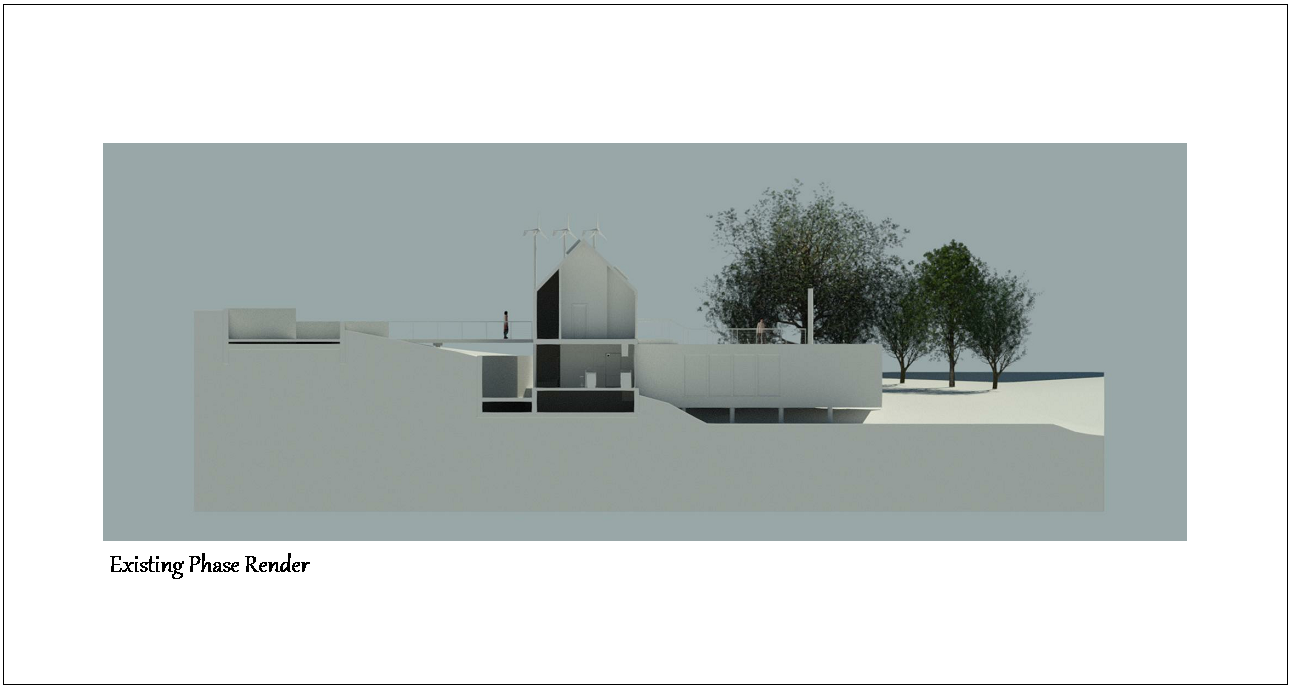
Modifying a scene's phasing properties and graphic overrides is however my favourite method: All elements in the scene, except for Planting, was added to the Existing Phase. The Existing Material was modified to a light grey.


Another interesting visualization method is to artificially manipulate a night render scene using a single light source. You will notice no exterior or interior lighting fixtures are turned on - The single light source is a huge studio light with its Photometric properties bumped up to quite an extent, elevated approximately 50 meters above the toposurface.


Revit also has the ability to render a scene with a transparent background. Any image can then be superimposed on the Revit scene. As I firmly believe life is too short to be serious all of the time, here is an example of what I believe Armageddon will look like. Enjoy the rest of your week folks!


Tuesday, 31 May 2016

Custom Entourage Family Twist

I'm sure that most readers of Revit Recess have wished that there is a bit more variety in the OOTB Entourage and even Planting content. This post will demonstrate that you do not only have to use the default families or purchase "better looking" ones - You are able to create your own.

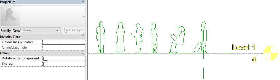
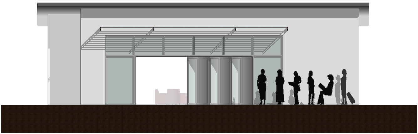
We will start by showing how to quickly create silhouettes from existing Revit Entourage families. All six female Entourage types were placed in a blank project and a section created orientated towards it. This section was then exported to a DWG file format and imported into a new Detail Item Family.

The DWG file was exploded and a solid black Filled Region was created using the pick lines command. All of the exploded DWG lines were deleted to retain only the Filled Region, as well as to keep the family size as small as possible. To ensure that no redundant data or annotations remain in the family, the Purge command was also run.

This Detail Item was nested into the Front View of a Genetic Model family. As a Detail Item family is a 2D object, a very simple symbol was drawn on Plan View to indicate the direction the person would be looking towards on a project Plan View.

All six female Entourage types were loaded and placed into an existing project. Looking good?

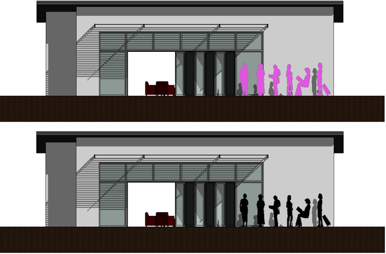
What about those occasions when you require your Entourage to be highlighted in a different colour? Simply select the Entourage family > Right Click > Select Override Graphics in View > By Category. Choose your colour, et voilĂ !

Changing your visual style to Realistic will however not retain the graphical override. Should you then wish to represent your Entourage in colour, you will need to use Phasing. 

This will only be a best-practice workflow if you are not using phasing on the project already, or if you create a copy of the live project for your visualization. By changing your Entourage to the Existing Phase and then modifying the Existing Phase's Graphic Overrides, you will be able to modify the Realistic Visual style's representation of your families.


Using the methods explained above with Revit 2017's Depth Cueing capabilities, creates quite a nice scene!

The second portion of this entry will show how a quick conceptual Planting family can be created, that is light in size, not detrimentally affecting your computer's performance, and minimizing the chance of causing your project to crash frequently. Does this sound familiar? Sketchup trees, AutoCAD 3D trees, exploded AutoCAD 2D trees.... 

The default Clump of Trees or Bushes AutoCAD block was imported into a Planting family Plan View, exploded and all DWG lines converted to Symbolic Revit lines. 


The tree geometry was created using extrusions and revolves, with materials applied to it. When seen in a project context, this example is not the prettiest (I'll admit that) but this fits perfectly into the conceptual design stage of a project.


Using a Hidden Lines Visual Style with Sketchy Lines enabled provides an acceptable result for me.