Search This Blog

Monday, 27 June 2016

Floor Plan View Range per Discipline

This quick Revit Recess entry will demonstrate the fundamental View Range graphics per Discipline. From the image below we will see a simple room which contains Architectural, Structural, and MEP elements.


Below is the result of changing the Level 1 Floor Plan's View Discipline to Architectural, with the following View Range settings:
     Primary Range:
             Top Range: Level Above with 2300mm Offset
             Cut Plane: 1200mm
             Bottom Range: Unlimited
     View Depth: 
             Level: Unlimited


The result of changing the Level 1 Floor Plan's View Discipline to either Mechanical, Electrical or Plumbing, with the following View Range settings:
     Primary Range:
             Top Range: Level Above with 2300mm Offset
             Cut Plane: 1200mm
             Bottom Range: Unlimited
     View Depth: 
             Level: Unlimited
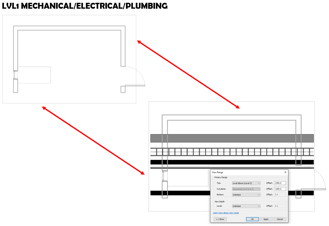

The result of changing the Level 1 Floor Plan's View Discipline to Structural, with the following View Range settings:
     Primary Range:
             Top Range: Level Above with 2300mm Offset
             Cut Plane: 1200mm
             Bottom Range: Unlimited
     View Depth: 
             Level: Unlimited

And lastly, the result of changing the Level 1 Floor Plan's View Discipline to Coordination, with the following View Range settings:
     Primary Range:
             Top Range: Level Above with 2300mm Offset
             Cut Plane: 1200mm
             Bottom Range: Unlimited
     View Depth: 
             Level: Unlimited


What can we then learn from the examples above? Create a dedicated Coordination Plan view, with the Discipline set to Coordination if any coordination needs to take place. Remember, the Coordination View Discipline is especially effective in a 3D view. Create and make use of filters to ensure turning services on and off is easy to do.

Monday, 13 June 2016

Alternative Visualization Methods

As Revit Recess is a blog investigating the workarounds in Revit, I have thought it would be apt to see what alternative methods one can use to create visualizations. In this entry we will investigate 5 alternative methods to create interesting visualizations in Revit, using only the default tools we get OOTB.

The first visualization example is to create a Mosaic using a combination of duplicated section views, each having their own and unique crop boundary, coupled with a visual style override for each view. The first image was created by duplicating a building section 11 times as a dependent. This allowed me to quickly change each dependent view's crop boundary in its parent view (Why can't we align or snap one crop boundary to another yet?). The challenge here was that if one changes the visual style of one view, all other dependent views' visual styles also change. 

To overcome the latter, all one needs to do is to duplicate each dependent view, as the crop boundary shape and location is retained. The second image shows all those duplicated views added together (Very much like adding Tetris blocks together - the views automatically aligns itself into position). 


The Mosaic visualization above can be taken even further: By creating a thin mosaic mass, with each mosaic section having its own shape and transparent colour, one can effectively add your own "filter" to a scene. Now this is where my ADD kicked in - What does the Refraction properties for materials really do? Below you will find the Refraction results for Air, Water, Alcohol, Quartz, Glass and Diamond. 


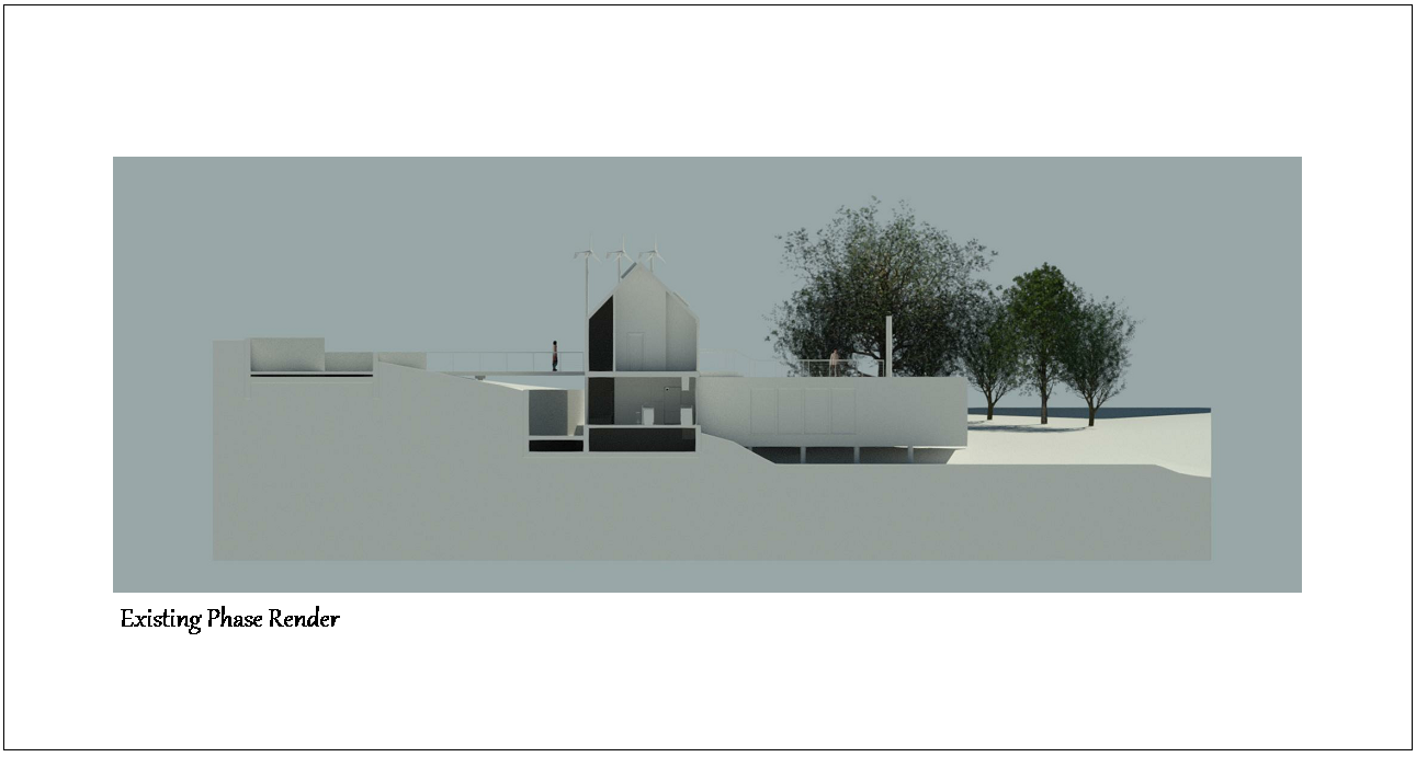
Modifying a scene's phasing properties and graphic overrides is however my favourite method: All elements in the scene, except for Planting, was added to the Existing Phase. The Existing Material was modified to a light grey.


Another interesting visualization method is to artificially manipulate a night render scene using a single light source. You will notice no exterior or interior lighting fixtures are turned on - The single light source is a huge studio light with its Photometric properties bumped up to quite an extent, elevated approximately 50 meters above the toposurface.


Revit also has the ability to render a scene with a transparent background. Any image can then be superimposed on the Revit scene. As I firmly believe life is too short to be serious all of the time, here is an example of what I believe Armageddon will look like. Enjoy the rest of your week folks!


Tuesday, 31 May 2016

Custom Entourage Family Twist

I'm sure that most readers of Revit Recess have wished that there is a bit more variety in the OOTB Entourage and even Planting content. This post will demonstrate that you do not only have to use the default families or purchase "better looking" ones - You are able to create your own.

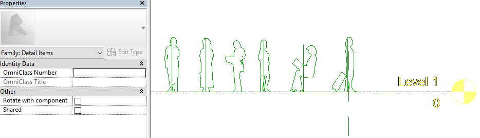
We will start by showing how to quickly create silhouettes from existing Revit Entourage families. All six female Entourage types were placed in a blank project and a section created orientated towards it. This section was then exported to a DWG file format and imported into a new Detail Item Family.

The DWG file was exploded and a solid black Filled Region was created using the pick lines command. All of the exploded DWG lines were deleted to retain only the Filled Region, as well as to keep the family size as small as possible. To ensure that no redundant data or annotations remain in the family, the Purge command was also run.

This Detail Item was nested into the Front View of a Genetic Model family. As a Detail Item family is a 2D object, a very simple symbol was drawn on Plan View to indicate the direction the person would be looking towards on a project Plan View.

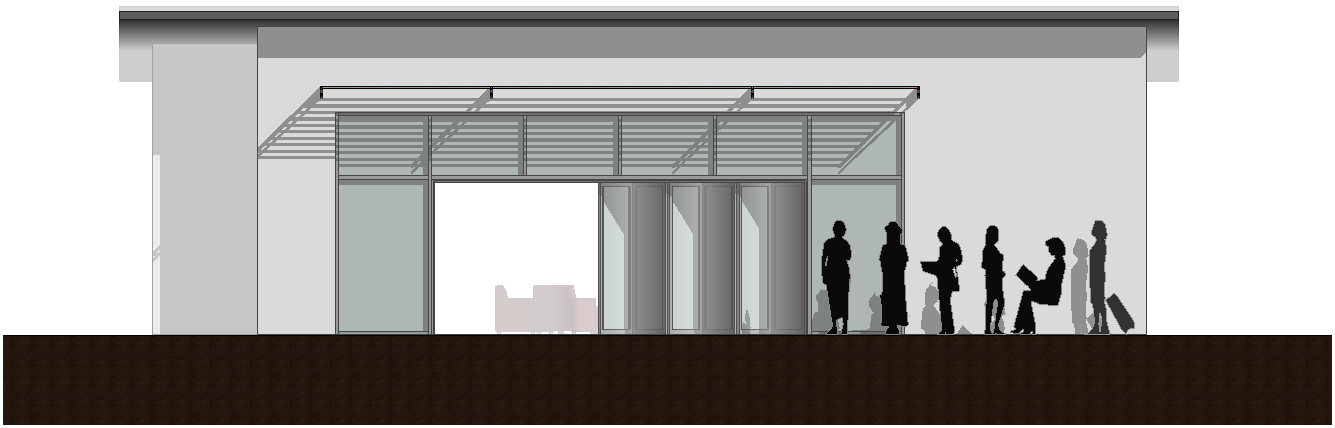
All six female Entourage types were loaded and placed into an existing project. Looking good?

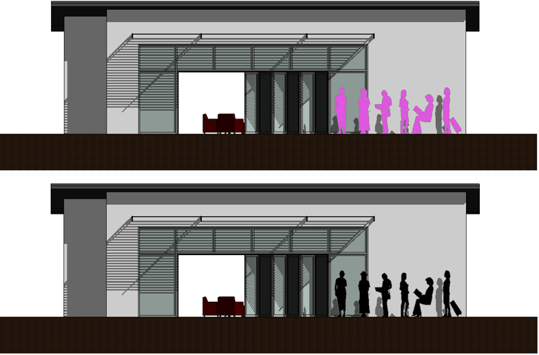
What about those occasions when you require your Entourage to be highlighted in a different colour? Simply select the Entourage family > Right Click > Select Override Graphics in View > By Category. Choose your colour, et voilĂ !

Changing your visual style to Realistic will however not retain the graphical override. Should you then wish to represent your Entourage in colour, you will need to use Phasing

This will only be a best-practice workflow if you are not using phasing on the project already, or if you create a copy of the live project for your visualization. By changing your Entourage to the Existing Phase and then modifying the Existing Phase's Graphic Overrides, you will be able to modify the Realistic Visual style's representation of your families.


Using the methods explained above with Revit 2017's Depth Cueing capabilities, creates quite a nice scene!

The second portion of this entry will show how a quick conceptual Planting family can be created, that is light in size, not detrimentally affecting your computer's performance, and minimizing the chance of causing your project to crash frequently. Does this sound familiar? Sketchup trees, AutoCAD 3D trees, exploded AutoCAD 2D trees.... 

The default Clump of Trees or Bushes AutoCAD block was imported into a Planting family Plan View, exploded and all DWG lines converted to Symbolic Revit lines. 


The tree geometry was created using extrusions and revolves, with materials applied to it. When seen in a project context, this example is not the prettiest (I'll admit that) but this fits perfectly into the conceptual design stage of a project.


Using a Hidden Lines Visual Style with Sketchy Lines enabled provides an acceptable result for me.

Friday, 20 May 2016

Revit 2016 / 2017 Render Comparison

This Revit Recess entry will focus on the differences between Revit 2017's render engine. as opposed to Revit 2016's NVIDIA mental ray and Autodesk Raytracer render engine. For more information on Revit 2016's different render engines, refer to this post.

I re-created a Go-Kart track based on a plan sourced from the internet (As everyone needs a change of scenery every now and again), It was a ton of fun to re-create this Go-Kart track in 3D, as I used the same railing creation principles for the tire barriers as shown in the Railing me this, Railing me that blog entry.


The renders I ran in Revit 2016 used both the NVIDIA mental ray, and Autodesk Raytracer render engines at a Draft, Low, Medium and High quality - The results of which can be seen below.


And now for the Revit 2017 renders: You will notice a clear similarity between these renders and the Autodesk Raytrace Revit 2016 renders. This is due to the fact that Autodesk's Raytracer render engine has been incorporated into the 2017 version by default.  

Wednesday, 18 May 2016

Clockwise or Clock(un)wise?

Every single time I train Revit users, I stress that the direction we draw in is of the utmost importance: Always draw in a clockwise direction. This Revit Recess post will use 3 examples where a clockwise direction of drawing (Or sketching, if you will) has definite advantages.

The first example will look at walls: If you sketch walls in a clockwise direction and then attach walls that has been drawn in an anticlockwise direction, your walls' interior and exterior finishes will be placed incorrectly. 

The same principle applies to the creation of sections. If you create a section in a clockwise direction, the section will always point to the "outside" as opposed to a anticlockwise sketch direction where the sections will point to the inside. 

One area where sketching in a clockwise direction really, really matters is for reference planes. The sketch direction of your reference planes will control the location of any element that is hosted to that reference plane. 

Even though the three examples above can be fixed quite quickly, it is unneeded steps. Even though an unneeded step might take one second, adding all the unneeded steps together might result in an hour lost per day.

Friday, 6 May 2016

CGI Master Artists - AREA by Autodesk

Once every month or so I tend to get lost for a few hours in a website called AREA by Autodesk. AREA is a infinite goldmine of images and knowledge if you are passionate about (or even have the slightest interest) in CGI. I love the user submissions - People like you and me who spend countless hours, weeks and months of their own free time to systematically learn how their software of choice works - Then refining their skills to such an extent that they are able to create absolutely insane results. 

In this Revit Recess post, I'd like to give credit to two particular artists: Joel Erkkinen and LĂ©andre HounnakĂ©. Joel was recognised as the December AREA Artist of the Month, with LĂ©andre HounnakĂ© the October AREA Artist of the Month.

In Joel's own words: 
"I really find humor in thinking about these iconic soldiers in every day situations. What do they do after work? What are their families like? What would they have as pets? While answering these questions with the renders, I like to include loads of detail and little "easter eggs" to keep the viewer engaged."

Léandre's images made my jaw literally drop. It's all I can say.


Do yourself a favour and visit Joel's company website: Meditech Communications, and LĂ©andre's webiste: Pixel23. Even better: If you do not have access to Autodesk's software, visit their product download pages and install a trial version. Play around with it, it's a whole lot of fun!

Wednesday, 4 May 2016

Level, Level, View!

As we all well know, everything in Revit is constrained to a level - Whether the bottom of an element, or the top of an element. We still need to tell Revit that a window has a Sill Height of, for example, 600mm above a Level. Similarly, we can also add a window with a Head Height of 1000mm below a Level. What will happen though if one should copy these windows from one level to another? This Revit Recess post will investigate the effects thereof. 

A simple project was created with windows placed. These windows have different elevation properties - The bottom windows have been placed with a Level Constraint of Level 1 (600mm Sill Height), with the upper windows having a Level Constraint of Level 2 (-2500mm Sill Height). 

By copying these windows in the elevation view from Level 1 to Level 2, something interesting occurs: The upper windows on level 2 now measures from Level 2, instead of from Level 3 - In other words, they are not constrained by Level 3, -2500mm.

Another interesting thing occurs when copying the windows located on Level 2, over to Level 3: The windows on Level 3 are now referencing Level 2, and extracting the Sill Heights from the level it is copied. 

There is actually a very simple explanation for this occurrence - Notice that the Level 3 Level Head in the images above is black. A black Level Head is a graphical notification that no Views have been assigned to that level: It is for reference purposes only, having Revit measuring the window Sill Heights from Level 2. 

Once a View has been created from Level 3, the windows will now reference the correct Level Constraint.

Now the question is: How will this affect the MEP discipline?

The long answer to this question is..... Only to a certain extent. Ducting, Piping, Cabletrays and Conduits have a built-in parameter called Reference Level. This parameter ensures that the elements are referencing the level it has been placed on, or copied to.

Mechanical, Electrical and Plumbing Equipment - Created from any un-hosted family template, will have a built in Host parameter. This Host parameter typically extracts the level the element is currently residing on. 

However, if any object is created from, for example, a Wall Based family template, the same behaviour applies as with Windows (Windows are also wall-based elements)

Monday, 18 April 2016

Where in the world is Herman?

Hello Revit Recess readers,

You might have wondered why my posts have become very infrequent. Fortunately work has been streaming in, so I had very little time available to play around on Revit.

I also had a bit of a bad experience recently with low-lives breaking into my flat and stealing both of my laptops and a number of other items I hold dear.

Please bear with continued infrequent updates, as I have lost all of my unpublished Revit Recess posts, even  my client and company files (Yes, my external backup drive was also pinched)

So, ja. I will be popping in now and again should I have some interesting or valuable content to share. I am pretty sure that we will soon see many posts focussing on the new Revit 2017 features!

Keep Calm and Revit on, Folks!

Herman Solomon 

Monday, 4 April 2016

Zaha Hadid


With a shock I read that Dame Zaha Hadid tragically passed away on 31 March 2016 from a heart attack - The Guardian. I simply do not have the words to describe the caliber of person she was, nor the impact she had on the Architectural world. Thus, I'd like to dedicate a poem to her - Written by the South African poet Jan F.E. Cilliers:


Stil, broers,
daar gaan 'n man verby,
hy groet,
en dis verlaas.
Daar's nog maar één soos hy;
bekyk hom goed.

Die oog,
nou dof en weggesink,
soos vuurvonk kon hy blink -
die arendsblik,
die kakie- en renegateskrik.
Die stap en kraggebaar
is nou bedaar.
Is dit jul leier nog, per' ruiterskaar?

Gewis!
en soos hy ons s'n was
en is.

Al is die oog verswak,
hy kyk nog fier omhoog
in jou
soos in sy God se oog.
Al stap hy kromgeknak
en afdraans af,
al klop die hart al flou:
soos altyd is nog nou
elk stap en hartslag trou
tot in sy graf.

En hierdie pure man
jou kind, Suid-Afrika!
Wat vrees ons dan?
Geseën sal wees
die grond, die bloed, die vlees
wat sulke vrugte dra.
In ons De Wet se gees
Voortwaarts,
Suid-Afrika!

Wednesday, 30 March 2016

Quick Color Fill Legend Tip

As can be seen from the frequency of my recent Revit Recess posts, I am lucky enough to be completely snowed under with work. So let's end March's blog entries with a quick time-saving tip for Color Fill Legends.

When you have a lot of data you need to show through a Color Fill Legend, by default we will have (1) a single column containing all of the information. When we decrease the Column length, we often notice that (2) the additional columns contain a lot of wasted space. (3) Manually editing these column widths does not take a long time, but in my books it's time you could have spent on something else. What are our workaround options then?

The workaround is actually very simple and quick to boot. (4) Adjust the column width of the Color Fill legend before you decrease the length. (5) Problem solved! 

Wednesday, 16 March 2016

Revit Error List Updated

6 New Revit errors have been added to the Revit Families_Error Compilation post.

Feel free to share your error experiences, or even to add a few typical or not-so-typical errors you have recently seen.

Friday, 4 March 2016

Revit versus FF&E's

Furniture and furnishings play an essential role in the use and operation of buildings. In addition to contributing to how users perceive and feel about a building, they are often necessary to achieve the functional requirements programmed for interior spaces. In essence, appropriate furniture and furnishings reinforce the design concept of the building. As well, functional and aesthetic FF&E solutions can enhance the appeal of the overall interior environment. The Architect’s Handbook of Professional Practice

Interior spaces and Revit are like two peas in a pod. This Revit Recess post will introduce Revit's capabilities for tagging FF&E's in different views using the Keynote command. As per the image below, a very simple 2-bedroom apartment was created.

We can create a custom Keynote file either through Notepad or Excel (There are other programs too) where we assign a Keynote Number to a FF&E object.

Should we need to tag the Furniture, Fixtures and Equipment, we can use the Keynote Tag command and choose a dedicated description or specification.

We have the ability to either show the Keynote number, or Keynote description in the Keynote tag.

Keynote tags can even be used in a 3D view.

The beauty of the Keynote functionality is that only the placed keynotes will show once the Keynote legend is placed on your sheet.

Friday, 26 February 2016

Ode to Homer Simpson

As an ode to the King of Procrastination, Revit Recess will forever immortalize Homer Simpson as a Conceptual Mass family.

"Don't eat me. I have a wife and kids. Eat them." - Homer Simpson

I sourced a few of literally thousands of Homer Simpson images from the internet, and got to work recreating his bust in Revit. Remember, best practice states that when we create a family in Revit, we draw the framework first, then add the geometry.


"It's not easy to juggle a pregnant wife and a troubled child, but somehow I managed to squeeze in 8 hours of TV a day." - Homer Simpson


I thought adding the geometry would be a tad more difficult, but I managed to achieve an acceptable result using only Revolves, Extrusions and Sweeps.


"Marge, can we go home? All this fresh air is making my hair move and I don't know how long I can complain." - Homer Simpson


A few materials were created and applied to the existing geometry. You might have noticed that Homer's nose is either broken, or I messed up my modelling. It was the latter (Very late night). I quickly fixed his nose this morning by replacing the extrusion with a sweep, as per the render to the top of this post. 


You might also ask yourself: "Why did Herman not fix the previous images?". The short answer is: I am way too lazy.

"All right, brain. You don't like me and I don't like you, but let's just do this and I can get back to killing you with beer." - Homer Simpson

Note: If you want to really see something impressive, head over to Kelvin Tam from REVIT SWAT's website, where he created Iron Man in Revit - Bloody impressive! 

Wednesday, 24 February 2016

Revit for Conceptual Urban Design

Connecting people and places - a Very rudimentary explanation about Urban Design, but quite apt in my opinion. Even though there are software packages available that are more suited to urban design, such as Autodesk Infraworks, conceptual urban design is still possible within Revit. This Revit Recess blog entry will focus on conceptual urban design within the Revit platform.

A very quick concept design can be created using the conceptual massing environment, complete with planting and roads. You will notice that I haven't paid particular attention to the road design or outlay from the images below. With the mass family loaded into the project, I thought that the Sketchy Lines functionality looks quite good as opposed to the standard Revit render or realistic visual style


Using a combination of Area Plans, Color Fill Legends and Project Parameters, it is quite easy to graphically indicate Open Spaces, Building Ownership & Zoning Plans, to name a few examples. Used in conjunction with schedules, the power of conceptual urban design in a BIM model is amplified to a large extent. 

As always, I always like to close off a blog entry with an Enscape Render, as I use this add-in 99% of the time I need to send quick rendered images to a client.