Search This Blog

Thursday, 30 April 2015

Anything but Revit

"It is easy to neglect your health and your family as you spend your time dealing with emergencies. Finding time for yourself or to think about the future of the business may seem just about impossible, but you won't be able to keep going at 100 miles per hour if you are running on empty" – Sir Richard Branson on Finding a Work-Life Balance

We live in a day and age where technology is constantly advancing. We are expected to do more in less time. We are expected to arrive earlier at work and to stay later at work to meet our deadlines. How often do you reply to emails after business hours? How often to you work at night to meet your deadlines (Self-imposed or not)? 


I do realize that I have a problem. I do not yet understand nor adhere to the line between my work and my personal life. One can argue that the client comes first. One can argue that if a client is working late due to deadlines, and they need immediate support to meet that deadline, I need to be on immediate standby to resolve that issue.


However, researchers have found that spending too long in the office resulted in a 40 to 80 percent greater chance of heart disease compared to an eight hour work day” 


Brian Dyson, CEO of Coca-Cola Enterprises, in his infamous 30-second speech, put things into perspective quite nicely:
“Imagine life as a game in which you are juggling five balls in the air. You name them – work, family, health, friends and spirit – and you’re keeping all of these in the air. You will soon understand that work is a rubber ball. If you drop it, it will bounce back.
But the other four balls – family, health, friends and spirit – are made of glass. If you drop one of these, they will be irrevocably scuffed, marked, nicked, damaged, or even shattered. They will never be the same.”


So this entry is all about everything but Revit. To break the mind-numbing monotony of certain work responsibilities, here is a list of my most frequently visited websites:


*** If you are easily offended or do not have a certain twisted sense of humor, I would advise not visiting these sites ***

  1. The Chive
  2. 9 GAG
  3. The Oatmeal
  4. Cyanide & Happiness
  5. Extra Fabulous Comics
  6. Idees Vol Vrees
  7. 27bslash6

Placeholder Sheets Explained

Placeholder sheets are an extremely useful tool which will allow you to pre-define Sheet Names and Sheet Numbers in your Revit Template. In other words, when creating a new sheet, you can simply select a sheet size, and apply the placeholder sheet information to the new sheet.

Placeholder sheets are created by browsing to the View Tab, Create Panel, Schedules Icon, and selecting the Sheet List command.

For the purpose of this entry, the only information that needs to be added to the Sheet List Schedule, are the Sheet Name and Sheet Number fields.


Data Rows (Pre-defined schedule properties) can now be added to the sheet list schedule, which after being populated, will become our placeholder sheets


When we now create a new sheet, we will be able to select the company standard sheet names and numbers. More data can be added to the sheet list schedule, which will obviously be huge time saver.

Wednesday, 29 April 2015

Fun with 5 Custom Staircase Designs

I had quite a bit of fun a few weeks ago, creating complex stairs in Revit. The challenge was not in the creation of these stairs, but to only access the commands we find in the project environment. Note that this excludes the use of an In-Place family. Everyone knows how I feel about in-place families...

Most of the complex stair examples shown below, was created from images on my favourite stair inspiration website: Stair Porn. Best to check with your network administrator whether the site will be blocked on not.

The first four stair designs will show two pictures each, the first being a Realistic Visual Style representation, and secondly a Rendered Image of the scene. 

The fifth staircase was quite challenging for someone working on custom stairs only once every few months, so detailed steps and images will be provided for the creation process.

Stair Challenge #1: Reception Desk Incorporated into Stair Treads


Stair Challenge #2: Concrete Spiral Stair with Center Post


Stair Challenge #3: Compact living storage staircase 


Challenge #4: Floating Wood Stair


Challenge #5: National Library of Greece Entrance Stair

* Remember: No in-place families were allowed in this challenge.
The first obstacle to overcome was that one cannot attach a wall's top base to a stair. This can only be done for Roofs, Floors, Ceilings and Walls

A dedicated floor was created to indicate the stair treads. This was done to allow the walls to attach to the tread's (Floor's) bottom.

Sketching out a separate floor per tread would have been a very tedious task, so I opted to create an radial array from the floor tread.

The treads were then aligned to the stair treads' top, to ensure that the elevations are correct. Because an array was created, the floor edges are not aligning to the exact tread positions.  

These floor edges were aligned as well.

Because the stair treads were created as floors, the wall's top bases can now easily be attached to the bottom of the treads.

This did take a bit of time to complete, because when one selects a wall and start the Attach Top Base command, the command must be run again each time an attachment needs to take place. Time wise, this process took about a quarter of a beer.

Custom railings were created, using balusters as well as baluster panels. 

A few additions were added to the staircase design, including a topography, road, planting, columns, etc. Time wise, this took about 3 quarters of a beer.

Even though the rendered image looks fine to me, the pedantic types out there will shout OVEREXPOSED! Keep in mind that the rendering time was another beer, and by that stage I just accepted the result.

Tuesday, 28 April 2015

Rotated Viewport Title

Recently I have received requests from users to provide the steps required for rotating a viewport title. 

Unfortunately, rotating a viewport title is not as cut-and-dry as one would expect. When selecting the viewport title, the Rotate command is inaccessible. Fortunately, there is a quick fix available

We need to remember that a viewport title is a Revit system family. In other words, the viewport title is created by the program in the project environment. Therefore, the first step is to find out which component families are embedded in the viewport title. One can verify the latter by selecting the Viewport Title, and editing the Type Properties. In the Title row, we can see that the M_View Title component family is used.

By editing the M_View Title family, one will now be able to rotate the View Labels,  and draw a line which will indicate the new viewport title line. Note that this viewport title line will not be editable in the project environment, so think about a realistic view title line length for all views that will be rotated on your sheets. (One obviously needs to save this family as "M_View Title_Rotated", to ensure you are not overriding your other viewport titles)

When loading the modified View Title family into your project, you will notice the new rotated view title line, complete with the original viewport title line still being visible. Look at the Type Selector in your Properties Panel. The Viewport type is set to "Title w Line".

Simply change the Viewport Type to "Title No Line" and your rotated viewport problems will be something of the past.

Parts - Division Profiles

Most users know about Revit's Parts functionality, even though they might not have used it before. If you do however need more information about the Parts function, you can refer to this blog entry. But did you know that you can also add pre-created division profiles to each divided part? When looking at the OOTB family templates, we will notice a dedicated Family Template called Division Profile. 

The default library will also contain some profiles, typically located in the Profiles folder, Division Profiles sub folder. If you have the South African library installed, herewith the full path: C:\ProgramData\Autodesk\RVT 2015\Libraries\South Africa\Profiles\Division Profiles 

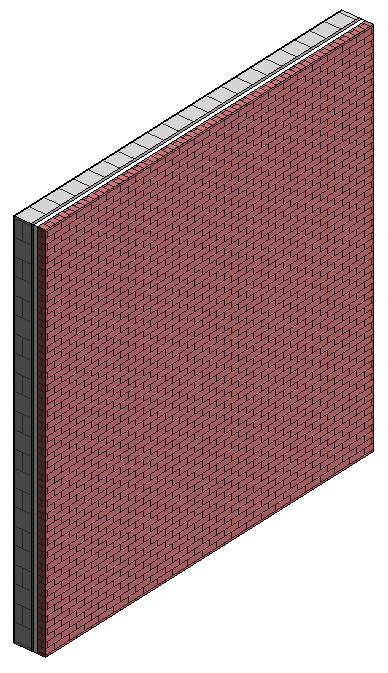
We will use the example of adding division profiles to a wall from which parts have already been created. 

The wall face has been divided into parts. The divided part will be divided again, in other words, broken into smaller portions.

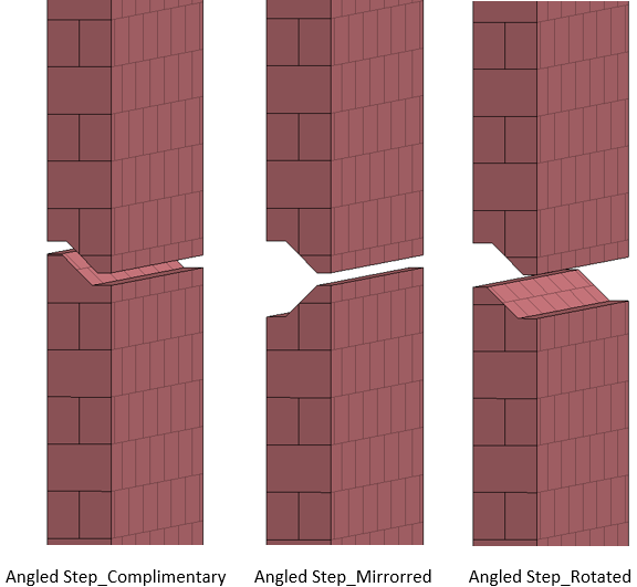
In the instance properties of the Divide Parts sketch, a Division Profile property will be visible, a Gap distance between the division, as well as an Edge Match property for the division.

For the purpose of this entry, we will look at the differences between the Angled Step Division Profile, and the Notch Division Profile, complete with all the Edge Match options we have for those Division Profiles.

Wednesday, 22 April 2015

Steampunk Revit

I have to admit, after researching some of Jules Verne's work, I have become an absolute Steampunk fanatic. Jules Verne and H.G. Wells are the founding fathers afterall. 

The term "Steampunk" is defined by Wikipedia as: 
"a subgenre of science fiction and sometimes fantasy—also in recent years a fashion and lifestyle movement—that incorporates technology and aesthetic designs inspired by 19th-century industrial steam-powered machinery. 

Although its literary origins are sometimes associated with the cyberpunk genre, steampunk works are often set in an alternative history of the 19th century's British Victorian era or American "Wild West", in a post-apocalyptic future during which steam power has maintained mainstream usage, or in a fantasy world that similarly employs steam power. Steampunk perhaps most recognisably features anachronistictechnologies or retro-futuristic inventions as people in the 19th century might have envisioned them, and is likewise rooted in the era's perspective on fashion, culture, architectural style, and art. Such technology may include fictional machines like those found in the works of H. G. Wells and Jules Verne, or the modern authors Philip Pullman, Scott Westerfeld, Stephen Hunt and China Miéville. Other examples of steampunk contain alternative history-style presentations of such technology as lighter-than-air airships, analogue computers, or such digital mechanical computers as Charles Babbage's Analytical Engine.

Steampunk may also incorporate additional elements from the genres of fantasyhorrorhistorical fiction, alternate history, or other branches of speculative fiction, making it often a hybrid genre. The term steampunk's first known appearance was in 1987, though it now retroactively refers to many works of fiction created even as far back as the 1950s or 1960s.
Steampunk also refers to any of the artistic styles, clothing fashions, or subcultures, that have developed from the aesthetics of steampunk fiction, Victorian-era fiction, art nouveau design, and films from the mid-20th century.[3]Various modern utilitarian objects have been modded by individual artisans into a pseudo-Victorian mechanical "steampunk" style, and a number of visual and musical artists have been described as steampunk."

The two rendered images below are of a simple room, "Steampunked" in Revit. Three different Steampunk families were created: a Table, Wall Clock, and a Writers Table. Steampunk Wallpaper was also added to all internal wall faces.


The Wall Clock family was created using a Generic Face-based family template. The clock hands and numbers were a fun challenge, due to the small size, and intricate forms. 

The Coffee (Read shot glasses) Table was created using the Generic Model family template.

The Writers Table was the most fun to create. Instead of assigning a material to the sweeps, extrusions and blends that were used, I opted to rather paint the faces of the geometric forms. It took a tad longer, but I am more than happy with this test result. 

I always tell my students, who are migrating from a 2D-based software platform to a 3D-based platform, to practice. As silly as it might sound, the more you practice, the better you get. The same principle applies to Revit. I am by no means an expert on Revit. There will ALWAYS be workarounds you have not yet discovered, or know about. However, whenever I have some free time (Read very, very late at night), I practice.

The entire world is available through the internet. Rather spend some time refining your skills by searching for Revit blogs, sites and forums, than stalking people on Facebook, Twitter, or Instagram. The more you know, the less frustrating problems you will have. Ergo, the less you will stress about project deadlines. Ergo, the more time you will spend with loved ones. 

And let's be honest: Creating the weird and wonderful in Revit is a whole lot of fun (And a huge ego-boost once you find the solution)!

Tuesday, 21 April 2015

DWG Export Layer Name Modifiers

Often one needs to add additional information to a Revit category when exporting to a DWG format. The information might differ from company to company, project to project, or even to indicate design intent.

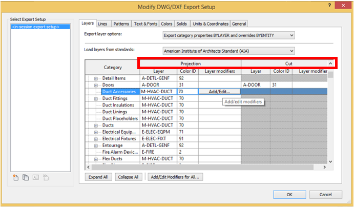
In the DWG/DXF Export Setup command, one will be able to change both the Projection, as well as Cut Layer properties. Remember, within a Revit view, we have a Cut Plane. This is typically set to 1200mm above the view’s level. Any Revit element below this Cut Plane (i.e. lower than 1200mm), will then be controlled by the Projection properties. Any Revit element above the Cut Plane (i.e. higher than 1200mm, and being cut by the plane) will then be controlled by the Cut properties.


(Note that MEP categories do not have Cut properties, as we need to see our ducting/cable trays/piping not only within the floor plan view, but also in the ceiling plan views, as an example)

One will be able to change both the Layer Names, as well as Index Colours for Revit categories. 

Layer modifiers will allow you to add additional information to layer names, such as:
  • Phase Created
  • Phase Demolished
  • Phase Status
  • System Classification
  • System Name
  • Underlay
  • View Type
  • Workset
    • As well as 3 customised layer modifiers.


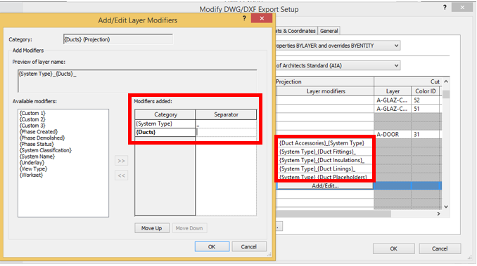
We will add layer modifiers to selected ducting categories, as per the example below. We will also add a separator between the two modifiers, to ensure that our AutoCAD layer names read correctly.

The end result will look as follows:

Thursday, 16 April 2015

Revit Material Classes and Assets

When it comes to Revit materials, there are quite a lot of options we can modify for both the class of materials used, as well as the material assets. This entry will discover and investigate the 16 material classes Revit provides, as well as their inherent asset properties. The image below is of a wall with 1m² material swatches. Each material class (Including each main asset category properties) will be applied sequentially to each swatch face.

The end result will look like the image below. Note that we will bump the asset properties up to the maximum for visual explanation purposes, so for the pedantic types out there, rather have a glass of wine while reading this post.

In the Materials Browser, Revit Material Classes can be found as indicated by 1 in the image below. Material Names (2) have been created from each of the classes. In 3, material assets have been duplicated and properties have been modified.
 

 Depending on the material class, we will have varying properties we can change. Some of the properties can be seen below, using the Fabric material class.

Material Class: Ceramic

Material Class: Concrete

Material Class: Fabric

Material Class: Flooring

Material Class: Gas

 Material Class: Glass

Material Class: Insulation

Material Class: Liquid

Material Class: Masonry

Material Class: Metal

Material Class: Misc

Material Class: Plaster

Material Class: Plastic

Material Class: Stone

Material Class: Tile

Material Class: Wood