Search This Blog

Wednesday, 30 March 2016

Quick Color Fill Legend Tip

As can be seen from the frequency of my recent Revit Recess posts, I am lucky enough to be completely snowed under with work. So let's end March's blog entries with a quick time-saving tip for Color Fill Legends.

When you have a lot of data you need to show through a Color Fill Legend, by default we will have (1) a single column containing all of the information. When we decrease the Column length, we often notice that (2) the additional columns contain a lot of wasted space. (3) Manually editing these column widths does not take a long time, but in my books it's time you could have spent on something else. What are our workaround options then?

The workaround is actually very simple and quick to boot. (4) Adjust the column width of the Color Fill legend before you decrease the length. (5) Problem solved! 

Wednesday, 16 March 2016

Revit Error List Updated

6 New Revit errors have been added to the Revit Families_Error Compilation post.

Feel free to share your error experiences, or even to add a few typical or not-so-typical errors you have recently seen.

Friday, 4 March 2016

Revit versus FF&E's

Furniture and furnishings play an essential role in the use and operation of buildings. In addition to contributing to how users perceive and feel about a building, they are often necessary to achieve the functional requirements programmed for interior spaces. In essence, appropriate furniture and furnishings reinforce the design concept of the building. As well, functional and aesthetic FF&E solutions can enhance the appeal of the overall interior environment. The Architect’s Handbook of Professional Practice

Interior spaces and Revit are like two peas in a pod. This Revit Recess post will introduce Revit's capabilities for tagging FF&E's in different views using the Keynote command. As per the image below, a very simple 2-bedroom apartment was created.

We can create a custom Keynote file either through Notepad or Excel (There are other programs too) where we assign a Keynote Number to a FF&E object.

Should we need to tag the Furniture, Fixtures and Equipment, we can use the Keynote Tag command and choose a dedicated description or specification.

We have the ability to either show the Keynote number, or Keynote description in the Keynote tag.

Keynote tags can even be used in a 3D view.

The beauty of the Keynote functionality is that only the placed keynotes will show once the Keynote legend is placed on your sheet.

Friday, 26 February 2016

Ode to Homer Simpson

As an ode to the King of Procrastination, Revit Recess will forever immortalize Homer Simpson as a Conceptual Mass family.

"Don't eat me. I have a wife and kids. Eat them." - Homer Simpson

I sourced a few of literally thousands of Homer Simpson images from the internet, and got to work recreating his bust in Revit. Remember, best practice states that when we create a family in Revit, we draw the framework first, then add the geometry.


"It's not easy to juggle a pregnant wife and a troubled child, but somehow I managed to squeeze in 8 hours of TV a day." - Homer Simpson


I thought adding the geometry would be a tad more difficult, but I managed to achieve an acceptable result using only Revolves, Extrusions and Sweeps.


"Marge, can we go home? All this fresh air is making my hair move and I don't know how long I can complain." - Homer Simpson


A few materials were created and applied to the existing geometry. You might have noticed that Homer's nose is either broken, or I messed up my modelling. It was the latter (Very late night). I quickly fixed his nose this morning by replacing the extrusion with a sweep, as per the render to the top of this post. 


You might also ask yourself: "Why did Herman not fix the previous images?". The short answer is: I am way too lazy.

"All right, brain. You don't like me and I don't like you, but let's just do this and I can get back to killing you with beer." - Homer Simpson

Note: If you want to really see something impressive, head over to Kelvin Tam from REVIT SWAT's website, where he created Iron Man in Revit - Bloody impressive! 

Wednesday, 24 February 2016

Revit for Conceptual Urban Design

Connecting people and places - a Very rudimentary explanation about Urban Design, but quite apt in my opinion. Even though there are software packages available that are more suited to urban design, such as Autodesk Infraworks, conceptual urban design is still possible within Revit. This Revit Recess blog entry will focus on conceptual urban design within the Revit platform.

A very quick concept design can be created using the conceptual massing environment, complete with planting and roads. You will notice that I haven't paid particular attention to the road design or outlay from the images below. With the mass family loaded into the project, I thought that the Sketchy Lines functionality looks quite good as opposed to the standard Revit render or realistic visual style


Using a combination of Area Plans, Color Fill Legends and Project Parameters, it is quite easy to graphically indicate Open Spaces, Building Ownership & Zoning Plans, to name a few examples. Used in conjunction with schedules, the power of conceptual urban design in a BIM model is amplified to a large extent. 

As always, I always like to close off a blog entry with an Enscape Render, as I use this add-in 99% of the time I need to send quick rendered images to a client. 

Thursday, 11 February 2016

Railing me this, Railing me that

Nostalgia can be defined as a "sentimentality for the past, typically for a period or place with happy personal associations. The word nostalgia is a learned formation of a Greek compound, consisting of Î½ÏŒÏƒÏ„ος (nóstos), meaning "homecoming", a Homeric word, and á¼„λγος (álgos), meaning "pain, ache", and was coined by a 17th-century medical student to describe the anxieties displayed by Swiss mercenaries fighting away from home. Described as a medical condition—a form of melancholy—in the Early Modern period, it became an important trope in Romanticism" - Wikipedia
People are resistant to change. This is normal. People are naturally afraid of the unknown and yearn for "those good old days" when designs were "simply" created with a pencil and sepia paper. I have a lot of respect for these old school skills; however, times are changing: In order to survive, we need to embrace change. Change is fun; Embrace technology to make your life easier. Never. Stop. Learning! 

This Revit Recess blog entry will investigate how Railings can be used to create completely different objects using different modelling and assembly methods.

1. How do you find a missing train? Follow the tracks


In this example, a railway track was created by creating a new railing profile and baluster family.

These families were used in the type properties of a newly created railing system family, by editing the Railing type properties. 

Tussen Treine - Richard van der Westhuizen & Gerhard Steyn

2. Where do forest rangers go to "get away from it all"?


Even though creating a forest natively in Revit might not be the best-practice option, it is possible and actually very easy to do. One can nest a planting family in a baluster family. The amount of planting RPC's will depend on how many rows of trees you require (Or how many times you need to replicate your treeline).  

I nested 5 Eastern Hemlock trees into a baluster family and created a new railing. Depending on the direction the rail is sketched, the trees will either be added on the left, right, top or bottom of your sketch line.

Suikerbos, Ek wil jou hê - Unknown musicians at the Brass Bell tunnel

3. Stay ahead of the curve


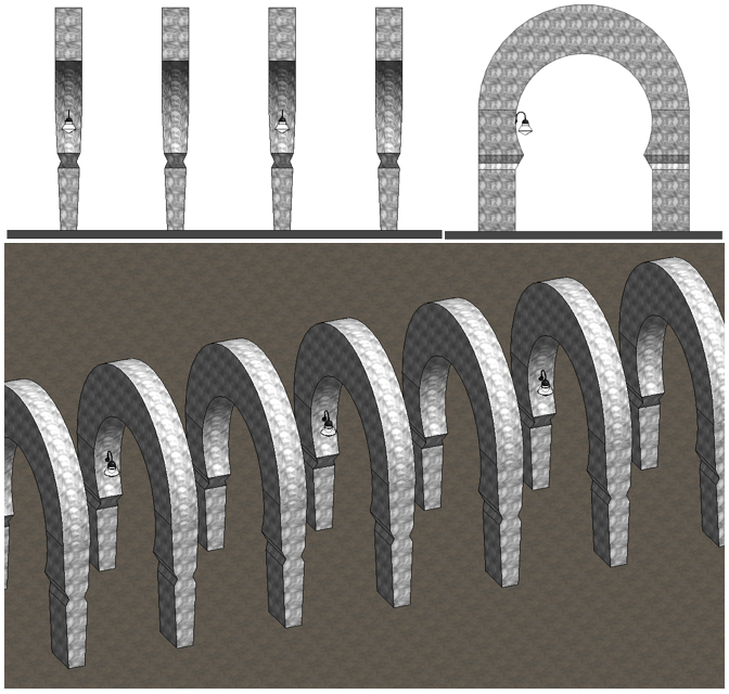
Using very similar nesting methods as described above, a simple horseshoe arch was created as a generic model family. This generic model family was nested into a new baluster family. You will notice that not every arch has a lighting fixture attached to it. Because we can set up multiple balusters per railing, all that was needed was to have an Arch-With-Light, and an Arch-Without-Light baluster family set up within the Type properties of the railing.


David Kramer - Stoksielalleen

Thursday, 4 February 2016

Conceptual Massing - Intersecting References

Revit's conceptual massing is often overlooked in lieu of an "old trusted" conceptual drawing program. In my opinion, if you want to be the best architect, the best engineer, the best CAD operator - you need to not only become an expert in your current software, but also have a very clear understanding of other software's capabilities.

So let's leave our Sketchup mindset at the door, just for a moment, and instill a mindset of: How can I apply this concept, this principle to that challenge, that problem - We are talking about conceptual design and modelling methods here, folks.

In this Revit Recess blog entry, we will play around in the conceptual massing environment - Specifically looking into Divided Surfaces' Intersect functionality. 

A simple form was created, constrained by reference planes.

What I would like to achieve, is for the form to be divided, i.e. create a custom grid, at locations I specify. 

By dividing the form's surface, I can now create a custom grid, through the Intersects command
The custom divided surface will now look as such:

We can even take it one step further and apply an existing divided surface pattern to my customized grid layout. The divided surface pattern will conform to the custom grid

The end result can look similar to the structure contained in the image below, but truth be told: The possible applications are endless!


Friday, 22 January 2016

Revit Work Plane Viewer

When working in the Conceptual Massing Environment, we often need to create very organic shapes using very specific profiles. However, as we can see from the image below, the location I would like to draw my profile on, is not parallel to any elevation view, will it be parallel to any point or corner on my View Cube.


To overcome the latter, we can active Revit’s Work Plane viewer, which can be found in the Create tab, Work Plane panel.


An extra window will open which is perfectly parallel to the point you would like to create a profile on. This Work Plane Viewer will allow all navigation, drawing, annotating and modifying commands to be done, with the exception of using keyboard shortcuts whilst working in the viewer.


The end result will be an extremely accurate, very accurate profile, which you can use to create any organic and unique forms.

Monday, 18 January 2016

Revit Symmetry

The Oxford Dictionary defines the term, symmetry as: “The quality of being made up of exactly similar parts facing each other or around an axis”. Symmetry forms such a big part of our daily lives that we rarely recognize or appreciate it anymore. This entry has been inspired by a recent post on Boredpanda, and will illustrate 3 examples of symmetry in that can be found in architecture and engineering (Even though a bit of Photoshop may be involved).

Each example was both easy and somewhat difficult to recreate in Revit. Sometimes the modelling methods needed to be revisited, and other times quite a few renders were needed to get a mildly acceptable result. Note: Renders were created through Revit as well as by using Enscape.


Buildings were created through the Conceptual Massing Environment, with walls and roofs applied to these mass faces. Curtain wall storefronts were added to the atrium. The biggest challenge was to “accurately” locate the perspective view from the entrance level looking up. Definitely not as simple as one would think!


I am however quite satisfied with the in-Revit conceptual render, using NVIDIA Mental Ray with custom render settings:

I really enjoyed toying with Enscape for this render, too. I ended up saving 14 images, of which I couldn’t decide which to post. So, to be fair, below is the first attempt

Floors, slab edges, split surfaces, railings and a generic model family were used to recreate the illuminated bridge. The generic model family’s material was set to be self-illuminating. The squares were arrayed, ungrouped and rotated in 15 degree increments.


Replicating the image to be as close to the original source took some time. Quite a number of in-Revit renders took place to get the illumination colour intensity and diffusion to be “acceptable”.

I do however prefer the Enscape render. It might just be because I am a huge TRON fan!

Our last example is of a non-parametric steel structure. I decided to create this as an in-place model, as by then, it was 3AM in the morning already. Sweeps and Extrusions were used.

The Revit Render result was quite dull, but I am sure with a few more tweaks, it would have looked much better. I just didn’t have enough time.


A subsequent goal of this blog post, is to illustrate the user-friendliness and quality of the Enscape software – Instant Immersive Visualization. Sometimes one simply does not have time to spare to run a number of renders for a presentation, making subtle changes to each render as you go along. This is where Enscape definitely fits the bill.

For more information on Enscape software, you can contact the sole representative in South Africa: Modena Design Centres at +27 11 463 1553, or send an email to sales@modena.co.za

Thursday, 7 January 2016

The History Behind Revit

This is an entry for the true Revit junkies out there. We will learn about the How, What, Where and Who of the Revit program - From 1997 to February 2002, when the founding company was purchased by Autodesk.


"SAN RAFAEL, Calif. and WALTHAM, Mass., Feb 21, 2002 (BUSINESS WIRE) -- Autodesk, Inc. (Nasdaq: ADSK), the leading design software and digital content company, today announced its intention to acquire Revit Technology Corporation, a Massachusetts-based developer of parametric building technology for building design, construction, and management, for $133 million cash. The addition of Revit software complements Autodesk's existing family of building industry applications with a parametric building modeler for customers to design, coordinate, and integrate information about an entire building. The closing of the acquisition is subject to governmental and shareholder approvals

The acquisition will extend our reach to new customers while expanding our existing building industry business," said Carol Bartz, Autodesk chairman and CEO. "Our product line will offer the best drafting and model-based design capabilities on the market, ultimately helping designers, builders, and owners better track and manage their building assets"


The following is an extract from Wikipedia, showing a brief history of the programme:
"Charles River Software was founded in Newton, Massachusetts, on October 31, 1997, by Leonid Raiz and Irwin Jungreis, key developers of PTC's Pro/Engineer software for mechanical design, with the intent of bringing the power of parametric modeling to the building industry (PTC had previously tried and failed to market its recently acquired Reflex software to the construction sector). With funding from venture capitalists Atlas Venture and North Bridge Venture Partners, Raiz and Jungreis hired several software developers and architects and began developing Revit in C++ on the Microsoft Windows platform. In 1999 they hired Dave Lemont as CEO and recruited board members Jon Hirschtick, founder of SolidWorks, and Arol Wolford, founder of CMD Group.

From the outset, Revit was intended to allow architects and other building professionals to design and document a building by creating a parametric three-dimensional model that included both the geometry and non-geometric design and construction information, which later became known as Building Information Modeling or BIM. At the time, several other software packages such as ArchiCAD and Reflex allowed working with a three-dimensional virtual building model, and allowed individual components to be controlled by parameters (parametric components). Two key differences in Revit were that its parametric components were created using a graphical "family editor" rather than a programming language, and all relationships between components, views, and annotations were captured by the model so that a change to any element would automatically propagate to keep the model consistent. For example, moving a wall would update the neighboring walls, floors, and roofs, correct the placement and values of dimensions and notes, adjust the floor areas reported in schedules, redraw section views, etc., so that the model would remain connected and all documentation would be coordinated. The concept of bi-directional associativity between components, views, and annotations was a distinguishing feature of Revit for many releases. The ease of making changes inspired the name Revit, a contraction of Revise-It. At the heart of Revit is a parametric change propagation engine that relied on a new technology, context-driven parametrics, that was more scalable than the variational and history-driven parametrics used in mechanical CAD software. The term Parametric Building Model was adopted to reflect the fact that changes to parameters drove the whole building model and associated documentation, not just individual components.

The company was renamed Revit Technology Corporation in January 2000, and Revit version 1.0 was released on April 5, 2000. The software progressed rapidly, with version 2.0, 3.0, 3.1, 4.0, and 4.1 released in August 2000; October 2000; February 2001; June 2001; November 2001; and January 2002, respectively. The software was initially offered only as a monthly rental, with no option to purchase. Licensing was controlled by an entirely automatic process, an innovation at a time when human intervention and manual transmission of authorization codes was required to buy other types of design software.

Autodesk (the developers of AutoCAD) purchased the Massachusetts-based Revit Technology Corporation for US$133 million in 2002. The purchase allowed more research, development and improvement of the software. Autodesk has released several versions of Revit since 2004. In 2005 Revit Structure was introduced, then in 2006 Revit MEP. After the 2006 release Revit Building was renamed Revit Architecture. Since Revit 2013 the different disciplines have been rolled into one product, simply called Revit. In 2012 Revit LT became the newest version of Revit on the market. It is a light version of Revit with a number of features such as rendering and multi user environments crippled. With their Revit platform, Autodesk is a significant player in the BIM market together with Nemetschek (makers of ArchiCAD, AllPlan and Vectorworks), and Gehry Technologies with CATIA based Digital Project."

Interesting, right?

Monday, 4 January 2016

Revit Opening Tools

There are a few opening tools in Revit which we can make use of. This blog entry will highlight these tools.

Opening by Face: This command will create an opening that is perpendicular to the selected face of a roof, floor, or ceiling

Shaft Opening: This command will create a vertical opening that spans multiple levels, cutting through intervening roofs, floors, and ceilings

Wall Opening: This command will cut a rectangular opening in a straight or curved wall
Vertical Opening: This command allows you to cut a vertical opening through a roof, floor, or ceiling

Dormer Opening: This command will cut a roof to create an opening for a dormer