A little known function in Revit, when one would like to determine the properties of a CAD layer, is called Query. We can access this function by selecting the CAD link, and navigating to our Import Instance Panel in the ribbon.
After starting the Query command and selecting any CAD line, the Import Instance Query window will activate. We will be able to determine the Block Name, Layer/Level, and Style By.
We will also be able to either Delete or Hide a specific Layer/Level in the view.
This is an extremely useful function we can utilize to manipulate the CAD drawing in Revit. However, this manipulation is completely dependent on the AutoCAD drawing's state of health. If AutoCAD Layers have not been used correctly, or not used at all, this Revit function will become moot.
Search This Blog
Friday, 27 November 2015
Wednesday, 25 November 2015
Changing Temporary Dimension Sizes
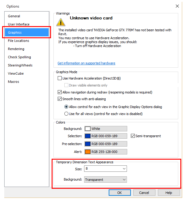
OOTB (Out Of The Box), temporary dimension sizes are 8mm, which can at certain levels of zoom be too small to select and change. Similarly, when trying to edit a temporary dimension on a very busy drawing, you might actually select model geometry. The Revit MEP folks will know exactly what I mean!
The results will look as per the image below:
Unfortunately, changing the temporary dimension size will not affect the size of MEP connectors - Only the graphical connector information.
This was, is, and will remain very high on my Revit wishlist for a future release.
Wednesday, 18 November 2015
DWF Markups in Revit - Design Review 2013
Autodesk Design Review 2013 is a very useful program which allows us to:
In Design Review, a number of markups can be made, as indicated by the images below
Once markups have been completed in Design Review, the DXF file can be linked back into Revit.
The DXF markup will be linked as an "overlay" onto the Revit sheet, which makes revising the project much easier, especially when working in the view through your sheet (Activating the view).
Autodesk Design Review 2013 can be downloaded by following this link.
Note: Even though the latest version of Autodesk Design Review is 2013, it is still widely used as the preferred markup tool
"Accelerate your design reviews on your desktop with Autodesk® Design Review software. It’s the free*, all-digital way to view, mark up, print, and track changes to Autodesk 2D and 3D files—without the original design software. Work with a wide variety of file formats, including DWF™ and DWFx, DWG™ and DXF™ (requires installation of free DWG TrueView™ software) and Adobe PDF, as well as several image file types including .bmp, .jpg, .gif, .pcx, .pct, .png, .rlc, .tga, .tif, .mil, .cal, and more." - AutodeskWe can export sheets to a DWF or DWFx format, which will then become readable in Design Review. This can be accomplished through the Application Menu.
In Design Review, a number of markups can be made, as indicated by the images below
Once markups have been completed in Design Review, the DXF file can be linked back into Revit.
Autodesk Design Review 2013 can be downloaded by following this link.
Note: Even though the latest version of Autodesk Design Review is 2013, it is still widely used as the preferred markup tool
Tuesday, 10 November 2015
How up-to-date is your Software?
More than often, when any client requests support for any software flavour, three main questions will be asked:
1. Have you installed the latest service packs for your software?
2. Have you installed the latest service packs for your OS (Operating System)?
3. Have you installed the latest drivers for your hardware?
These questions might seem like silly questions. However, once confirmation has been received that these have been attended to, one can start looking at other reasons why software has been crashing, is performing slowly, or why the user cannot perform a command.
One can update all Autodesk software through the Autodesk Application Manager. I have actually pinned by Application Manager to my Windows taskbar.
A little tip if you have a myriad of Autodesk software products to update: We have the option to sort all updates to Severity. This will ensure that the most important updates will be listed to the top of the Application Manager.
1. Have you installed the latest service packs for your software?
2. Have you installed the latest service packs for your OS (Operating System)?
3. Have you installed the latest drivers for your hardware?
These questions might seem like silly questions. However, once confirmation has been received that these have been attended to, one can start looking at other reasons why software has been crashing, is performing slowly, or why the user cannot perform a command.
One can update all Autodesk software through the Autodesk Application Manager. I have actually pinned by Application Manager to my Windows taskbar.
A little tip if you have a myriad of Autodesk software products to update: We have the option to sort all updates to Severity. This will ensure that the most important updates will be listed to the top of the Application Manager.
Thursday, 5 November 2015
Revit 2016 Release 2 - Autodesk Raytracer Improvements
In the latest Release for Revit 2016: Release 2, Autodesk Raytracer has been improved to a large extent. One is now able to control not only the Rendering Quality, but also the Light and Material Accuracy as well as the Render Duration.
1. When choosing Autodesk Raytracer as your render engine, and Customizing your render settings, you will be able to Edit these settings.
2. In the Render Quality Settings window, you can choose whether your Light and Material Accuracy should be Simplified, or be set to Advanced
3. Render Quality can be set to one of three options:
3.1 Render by Level (1 - 40)
3.2 Render by Time: 32768 minutes / 546.133 Hours / 22.76 Days
3.3 Render until Satisfactory
Comparison Example: Render Level 1 versus Render Level 20:
Comparison Example: Render by Time - 1 Minute versus 10 Minutes
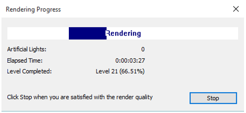
Example: Render Until Satisfactory
Friday, 30 October 2015
Project Shapeshifter to Revit Conceptual Design
Project Shapeshifter is a free Autodesk technology preview providing an easy way to create complex 3D printable models in your web browser - Project Shapeshifter Facebook Page
After playing around with Project Shapeshifter, I have to say I am quite impressed. Extremely complex geometrical forms can be created, which would take a considerable amount of time to replicate in Revit's massing environment, as well as through visual programming in Dynamo. I wondered how one could utilize these Project Shapeshifter forms in Revit and started defining a workflow.
The first images below will demonstrate the various forms one can create in Project Shapeshifter, based on the pre-existing templates.
The Cube template will be active by default. There is a filmstrip to the bottom of the web browser which allows you to choose from 38 patterns, and apply those patterns to the object.
Below are the different patterns which can be applied, and their effects:
The various forms one can choose from, takes place from the templates tab to the top of the web browser. There are 12 forms to choose from.
A snake form was chosen. One can now start to modify basic settings applicable to this form, or even move to more advanced settings. One can even decide what the form geometry will look like: Based on a circle, half circle, triangle, etc.
The best feature for me would be the Randomize function. You will get a random form with a random pattern and random template applied. This shapeshifter model can then be downloaded in either a *.obj file format, or *.stl file format. With a quick file format conversion in 3ds Max to ACIS Sat, the concept is useable in Revit.
Walls and Curtain Systems were applied to the form faces, to generate quite an interesting structure:
Tuesday, 27 October 2015
View Anomaly
A client recently contacted me with a very interesting observation, a view anomaly if you will. Whilst setting up his template, he created a company standard callout. When window selecting the callout, Revit showed he had 1 callout selected. However, when selecting all callouts in the view, he suddenly had 2 callouts. He could not find the "ghost" callout, nor could I.
Below is an example of the view amounts when window-selecting the callout, detail section, and building section:
This is where things get interesting: When selecting all callouts, detail sections and building sections in the view, we now have twice as many views
A view list schedule confirms that we only have one of each type
Below is an example of the view amounts when window-selecting the callout, detail section, and building section:
This is where things get interesting: When selecting all callouts, detail sections and building sections in the view, we now have twice as many views
A view list schedule confirms that we only have one of each type
After a bit of investigation, we saw that the Crop Boundary for each view is also seen by Revit as a View, which kind of makes sense. So there you have it: A section, for example, is actually two views - the section itself, as well as the crop region.
Friday, 23 October 2015
Revit 2016 R2 Available for Download
Revit 2016 Release 2 has been made available for download.
Steve's blog: Revit OpEd, lists the enhancements for which Autodesk created videos (The link is also provided in his blog entry). Additional information about the new release can also be found at In The Fold, Autodesk's Public Relations site
As far as I can see there is nothing to jump up and down for about the Mechanical and Electrical enhancements, but I will verify this over the weekend and give some feedback in a future post.
Steve's blog: Revit OpEd, lists the enhancements for which Autodesk created videos (The link is also provided in his blog entry). Additional information about the new release can also be found at In The Fold, Autodesk's Public Relations site
As far as I can see there is nothing to jump up and down for about the Mechanical and Electrical enhancements, but I will verify this over the weekend and give some feedback in a future post.
Wednesday, 21 October 2015
The Revit Catacomb
"Without change there is no innovation, creativity, or the incentive for improvement. Those who initiate change will have a better opportunity to manage the change that is inevitable" - William Pollard
This entry is based on a mobile android game called SoulCraft, developed by MobileBits. As I was playing the game, I entered the Egyptian tomb level and I thought: It might be a fun exercise to recreate this Egyptian tomb in Revit.
Below are two screenshots of the level's environment, using my cellphone's screenshot function:
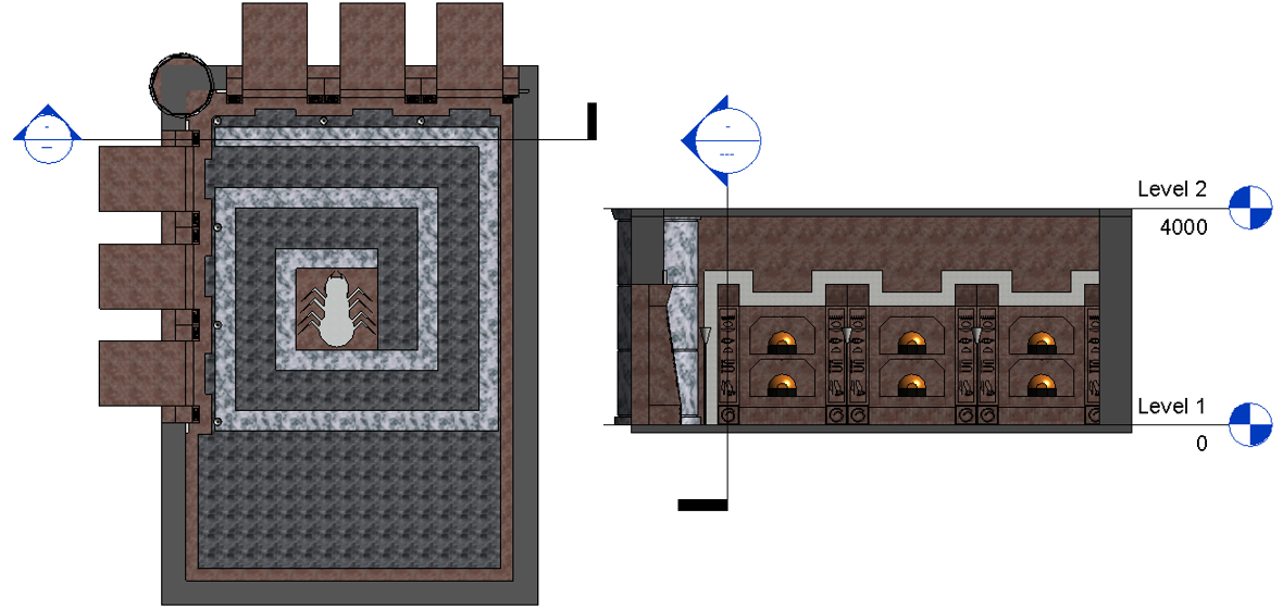
Based on the latter images, a mock catacomb was created with the following rendered result:
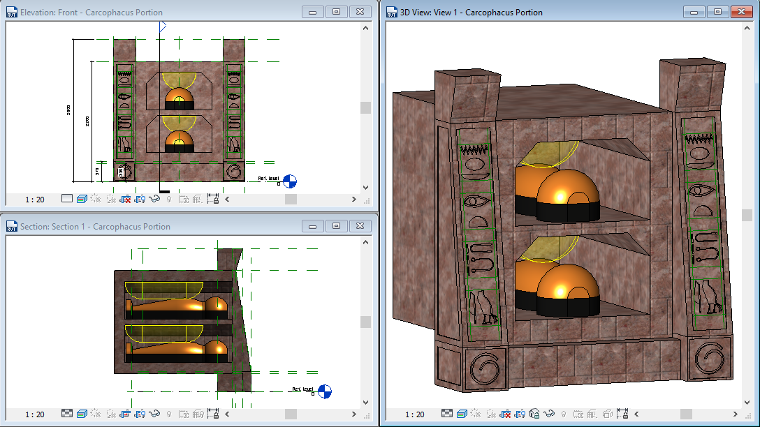
The burial niches were created as Generic Model families, with the Family Category changed to Window when it was complete. Due to the category change, it was possible to add an opening cut to the niches. A recessed light source was also placed above the niches for illuminating the opening, and respective sarcophagi. I was able to etch the Egyptian symbols into the tapered column by sketching it out using voids.
Splitting the floor face enabled me to apply two materials to each segment to indicate the different floor finishes. The trim around the wall niches were created using an in-place sweep.
Enabling the Light Sources in a realistic view, provided a good indication of how the light distribution would look in the rendering.
See? It's not necessary to only Revit during working hours. Have fun!
Monday, 19 October 2015
Mosaic Floor Desi... Hey look, a chicken!
Originally, this entry was intended to discuss the advantages and disadvantages of designing a feature mosaic floor using an image, as opposed to modelling each and every single tile complete with grouting. However, it seems I have developed a mild case of ADD so this entry morphed into something else.
You might already ask: Why on earth do you want to model each and every tile? If I really, really need to know the amount of tile variations and volume of grouting, I would rather obtain it from the flooring specialist. I complete agree with the latter statement.
The first example sourced from the internet will focus on applying an image to a floor's material.
The advantage of using this method is that it will take 5 minutes to set up. The disadvantage is that one will not see the tiling layout unless we are in a Realistic visual style (There is however a very simple a quick fix to this). All that needs to be done is to create a new material name, material asset, and apply the mosaic floor image to the material. Some image offset values might need to be adjusted, as the image might not be perfectly centered.
The end result may look like the image below:
Now, at this point my ADD kicked in: I thought about the scheduling of these mosaic tiles and how much grouting would be required (Just in case I do not trust the flooring specialist). I created a copy of the mosaic floor, and traced each tile. Where possible, arrays were created either as an array to second, or array to last. Displaced element sets were created with 50mm height increments.
A material takeoff schedule was created to verify the amount, area, and volume of tiles and grouting required
But then I thought, how great would it look to make this mosaic floor a true feature showcase floor. Incremental offset values were added to each "ring" of tiles, with 10mm rods added to each tile set.
Was it worth all of the time and work? Yes, it looks pretty. But do you really have 6 hours to spare on a live project to play around with a "nice to have"?
You might already ask: Why on earth do you want to model each and every tile? If I really, really need to know the amount of tile variations and volume of grouting, I would rather obtain it from the flooring specialist. I complete agree with the latter statement.
The first example sourced from the internet will focus on applying an image to a floor's material.
The advantage of using this method is that it will take 5 minutes to set up. The disadvantage is that one will not see the tiling layout unless we are in a Realistic visual style (There is however a very simple a quick fix to this). All that needs to be done is to create a new material name, material asset, and apply the mosaic floor image to the material. Some image offset values might need to be adjusted, as the image might not be perfectly centered.
The end result may look like the image below:
Now, at this point my ADD kicked in: I thought about the scheduling of these mosaic tiles and how much grouting would be required (Just in case I do not trust the flooring specialist). I created a copy of the mosaic floor, and traced each tile. Where possible, arrays were created either as an array to second, or array to last. Displaced element sets were created with 50mm height increments.
A material takeoff schedule was created to verify the amount, area, and volume of tiles and grouting required
But then I thought, how great would it look to make this mosaic floor a true feature showcase floor. Incremental offset values were added to each "ring" of tiles, with 10mm rods added to each tile set.
Tuesday, 13 October 2015
An Alternative Browser Organization
A well set up browser organization will save you many hours of work. Rather than searching through hundreds of views, we are able to categorize those views according to either our own, or the project's standards.
There is however an alternative to using Revit's default browser organization: View Types. As can be seen from the image below, the default browser organization lists all Views according to their View Types: Floor Plans, Ceiling Plans and Elevations.
Below is a quick example of a browser organisation that has been edited to include floor plans for both Working Drawings, as well as Council Submission drawings.
Wednesday, 7 October 2015
Curtain Wall Mullion Types
This blog entry will focus on the different Curtain Wall Mullion Types we have access to in the default Revit program. Additional to the Rectangular and Circular curtain wall mullions, we also have access to different types of Corner mullions, namely:
- L Corner Mullion
- Quad Corner Mullion
- Trapezoid Corner Mullion
- V Corner Mullion
I have created a very simple greenhouse using sloped glazing for the roof. Tip: Using L Corner mullions on the ridge, will make it look like V Corner Mullions were applied.
As always, one tends to get diverted when playing around with Revit. I aimed to create a very short introduction to the different types of mullions, and ended up adding parametric openable curtain panel windows, pots and planting. Such is life.
- L Corner Mullion
- Quad Corner Mullion
- Trapezoid Corner Mullion
- V Corner Mullion
I have created a very simple greenhouse using sloped glazing for the roof. Tip: Using L Corner mullions on the ridge, will make it look like V Corner Mullions were applied.
As always, one tends to get diverted when playing around with Revit. I aimed to create a very short introduction to the different types of mullions, and ended up adding parametric openable curtain panel windows, pots and planting. Such is life.
Subscribe to:
Posts (Atom)