Search This Blog

Wednesday, 6 May 2015

Complex Revit Roof Designs

Complex roof designs in any software program is more often than not a huge headache for users. Some of my clients wish that the same functionality of AutoCAD can be applied to Revit roofs. However, that wish only lasts until they find that one can also modify a roof’s sub-elements, add splitlines and override the roof lines with invisible lines. 

We will use the example of a complex roof that was created in AutoCAD, and now needs to be converted to a three dimensional Revit roof. 

The AutoCAD roof footprint was linked into Revit and the Roof By Footprint command was started. It is quite important to to remember to create the complex roof as a flat roof with no slopes applied.


After the roof footprint is created, the Sub Elements of the roof can now be modified: Adding elevation points, adding split lines, as well as picking supports for the new roof.

Split lines (in Blue) with positive elevation values were added to indicate the roof ridges. The roof boundary lines are shown in green.

As can be seen from the image below, Revit has now added valley and hip lines between the modified sub element points. More often than not, these lines are incorrect (It seems like Revit triangulates the roof face). How do we fix this?

There is always a workaround in Revit. In the Modify tab, View panel, we will find the Linework Override command. 


By choosing the Invisible Lines option, we can control which roofing lines should be hidden and which lines should be visible. Please note that this is a view-specific override, thus any view in which the roof is visible, will have to be prepared using the same method.

Monday, 4 May 2015

Revit Families_Error Compilation

I have experienced quite a few typical, strange, funny and even downright silly Revit errors over the years. I am sure you have as well!

I invite you to submit your weird and wonderful Revit errors in the comments below. If we build up a record of these errors, it will be much easier to solve (And we will have some referencing material). This blog entry will constantly be updated with the typical and not-so-typical errors we come across, and their solutions (Once we know about it)


The first portion of the entry will focus on the typical errors we find in the family creation environment.


Error 1: "There is a circular chain of references among the formulas"

     Explanation: You are referencing a parameter with itself
     Solution: Create a driving/user input parameter

Error 2: "The following is not a valid family parameter:..."
     Explanation: The parameter does not exist
     Solution: Parameters are case and syntax sensitive. Check syntax and parameter case

Error 3: "Unexpected end of expression"
     Explanation: Not enough brackets at end of formula
     Solution: Add more brackets to end of formula

Error 4: "Right parenthesis not expected"
     Explanation: Too many brackets at end of formula
     Solution: Remove brackets at end of formula

Error 5: "Bad IF-statement format. It should be IF (<boolean>,<result if true>,<result if false>)"
     Explanation: Formula incorrect
     Solution: Verify formula composition

Error 6: "Inconsistent Units"
     Explanation: Formula has incompatible parameter types
     Solution: Either change parameter types, or modify formula to take parameter types into account

Error 7: "Constraints are not satisfied"
     Explanation: Geometry and/or Reference Planes have been locked to set value/parameter/location
     Solution: Either remove constraints, or re-constrain geometry/reference plane/reference line

Error 8: "Last type in system family 'Stacked Wall' cannot be deleted"
     Explanation: Sometimes happen when upgrading families from a previous version to a newer version. Parameter/Family corrupt. Similarly, if multiple users are working on the family, with different service packs installed, chances of this error occurring increases.
     Solution: Ensure all Revit programs are on the same Service Pack. Purge and audit family. Ensure families are upgraded each release. Recreating the family might be required

Error 9: "Operator not expected:..."
     Explanation: One cannot have "<=" in a formula. Revit only sees the first operator: <
     Solution: Adjust formula to take the two conditions into account

Error 10: "Parameter 'NAME' has an invalid value"
     Explanation: An array contains a minimum of two arrayed elements
     Solution: Change array driving parameter value, or add a minimum array number constraint to formula

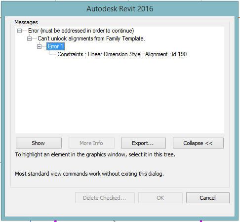
Error 11: "Can't unlock alignments from Family Template"
     Explanation: Constraints specified in family template by family category
     Solution: Breaking the constraint manually will resolve error.

Error 12: "Locking this dimension would overconstrain the sketch"
     Explanation: More than one dimension referencing the same elements have been created and you are trying to lock said dimension.
     Solution: Make sure that no other dimensions referencing the same elements exists in the same, or another view

Error 13: "Can't make cut-out"
     Explanation: Opening cut in family template not cutting through solid geometry anymore.
     Solution: Ensure that solid geometry is still being cut by opening.

Error 14: "Element is too small on screen"
     Explanation: Revit can only draw elements more than 0.8mm in length.
     Solution: Make line 0.8mm or longer. Sometimes an equation does force an object to be smaller than 0.8. One can edit either a permanent dimension, temporary dimension or use the move command. Example: line needs to be 0.6mm - Move line 1mm from origin>Start move command and move line back with formula: "=1.6-1.0"

Sometimes one can access a More Info command on the error dialogue itself. This will direct you to the relevant help topic, as indicated by the image below.

Error 15: "Incorrect number of arguments to function"
     Explanation: The formula currently being used needs another condition or value.
     Solution: Verify formula composition.

Error 16: "Performance Warning: This family now contains both labeled dimensions and sketches with many segments..."
     Explanation: Too many sketches exist within the same family. Typically happens when you have a lot of complex geometry that uses many line segments (E.g. many multi-segmented polygonal forms, or sweeps constructed of many short splines segments) 
     Solution: As per the warnings dialogue, rather create separate families (Sub-assemblies) and embed/nest those in the main family (Assembly)

Error 17: "While loading '<Family Name>': Shared detail components cannot be used in 3d model families"
     Explanation: Making a nested family Shared, will allow it to be schedulable in the project environment. However, you cannot nest a Shared detail item family in a 3D family.
     Solution: Nest the Detail Item family in a 3D family, which can be made to be shared, and in turn be nested into another 3D family.
Error 18: "While loading '<Family Name>': Only the following kinds of families can be loaded into a detail family:
- Detail families
- Generic Annotations"
     Explanation: One cannot use a 3D family in a 2D family template
     Solution: Rather load a 2D family into a 3D family.

Error 20: Sketch-based command errors
Error 20.1: "Lines must be in closed loops. The highlighted lines are open at one end".
     Explanation & Solution: Most sketch-based commands require one continuous closed loop/border/boundary. Join the boundary lines.

Error 20.2: "Lines cannot intersect each other. The highlighted lines currently intersects".
     Explanation & Solution: Most sketch-based commands require one continuous closed loop/border/boundary. Trim the boundary lines.

Error 20.3: "Cannot have overlapping lines".
     Explanation & Solution: Most sketch-based commands require one continuous closed loop/border/boundary. Find the area where two or more lines are overlapping, and delete all overlapping lines.

Thursday, 30 April 2015

Anything but Revit

"It is easy to neglect your health and your family as you spend your time dealing with emergencies. Finding time for yourself or to think about the future of the business may seem just about impossible, but you won't be able to keep going at 100 miles per hour if you are running on empty" – Sir Richard Branson on Finding a Work-Life Balance

We live in a day and age where technology is constantly advancing. We are expected to do more in less time. We are expected to arrive earlier at work and to stay later at work to meet our deadlines. How often do you reply to emails after business hours? How often to you work at night to meet your deadlines (Self-imposed or not)? 


I do realize that I have a problem. I do not yet understand nor adhere to the line between my work and my personal life. One can argue that the client comes first. One can argue that if a client is working late due to deadlines, and they need immediate support to meet that deadline, I need to be on immediate standby to resolve that issue.


However, researchers have found that spending too long in the office resulted in a 40 to 80 percent greater chance of heart disease compared to an eight hour work day” 


Brian Dyson, CEO of Coca-Cola Enterprises, in his infamous 30-second speech, put things into perspective quite nicely:
“Imagine life as a game in which you are juggling five balls in the air. You name them – work, family, health, friends and spirit – and you’re keeping all of these in the air. You will soon understand that work is a rubber ball. If you drop it, it will bounce back.
But the other four balls – family, health, friends and spirit – are made of glass. If you drop one of these, they will be irrevocably scuffed, marked, nicked, damaged, or even shattered. They will never be the same.”


So this entry is all about everything but Revit. To break the mind-numbing monotony of certain work responsibilities, here is a list of my most frequently visited websites:


*** If you are easily offended or do not have a certain twisted sense of humor, I would advise not visiting these sites ***

  1. The Chive
  2. 9 GAG
  3. The Oatmeal
  4. Cyanide & Happiness
  5. Extra Fabulous Comics
  6. Idees Vol Vrees
  7. 27bslash6

Placeholder Sheets Explained

Placeholder sheets are an extremely useful tool which will allow you to pre-define Sheet Names and Sheet Numbers in your Revit Template. In other words, when creating a new sheet, you can simply select a sheet size, and apply the placeholder sheet information to the new sheet.

Placeholder sheets are created by browsing to the View Tab, Create Panel, Schedules Icon, and selecting the Sheet List command.

For the purpose of this entry, the only information that needs to be added to the Sheet List Schedule, are the Sheet Name and Sheet Number fields.


Data Rows (Pre-defined schedule properties) can now be added to the sheet list schedule, which after being populated, will become our placeholder sheets


When we now create a new sheet, we will be able to select the company standard sheet names and numbers. More data can be added to the sheet list schedule, which will obviously be huge time saver.

Wednesday, 29 April 2015

Fun with 5 Custom Staircase Designs

I had quite a bit of fun a few weeks ago, creating complex stairs in Revit. The challenge was not in the creation of these stairs, but to only access the commands we find in the project environment. Note that this excludes the use of an In-Place family. Everyone knows how I feel about in-place families...

Most of the complex stair examples shown below, was created from images on my favourite stair inspiration website: Stair Porn. Best to check with your network administrator whether the site will be blocked on not.

The first four stair designs will show two pictures each, the first being a Realistic Visual Style representation, and secondly a Rendered Image of the scene. 

The fifth staircase was quite challenging for someone working on custom stairs only once every few months, so detailed steps and images will be provided for the creation process.

Stair Challenge #1: Reception Desk Incorporated into Stair Treads


Stair Challenge #2: Concrete Spiral Stair with Center Post


Stair Challenge #3: Compact living storage staircase 


Challenge #4: Floating Wood Stair


Challenge #5: National Library of Greece Entrance Stair

* Remember: No in-place families were allowed in this challenge.

The first obstacle to overcome was that one cannot attach a wall's top base to a stair. This can only be done for Roofs, Floors, Ceilings and Walls

A dedicated floor was created to indicate the stair treads. This was done to allow the walls to attach to the tread's (Floor's) bottom.

Sketching out a separate floor per tread would have been a very tedious task, so I opted to create an radial array from the floor tread.

The treads were then aligned to the stair treads' top, to ensure that the elevations are correct. Because an array was created, the floor edges are not aligning to the exact tread positions.  

These floor edges were aligned as well.

Because the stair treads were created as floors, the wall's top bases can now easily be attached to the bottom of the treads.

This did take a bit of time to complete, because when one selects a wall and start the Attach Top Base command, the command must be run again each time an attachment needs to take place. Time wise, this process took about a quarter of a beer.

Custom railings were created, using balusters as well as baluster panels. 

A few additions were added to the staircase design, including a topography, road, planting, columns, etc. Time wise, this took about 3 quarters of a beer.

Even though the rendered image looks fine to me, the pedantic types out there will shout OVEREXPOSED! Keep in mind that the rendering time was another beer, and by that stage I just accepted the result.