Search This Blog

Monday, 27 June 2016

Floor Plan View Range per Discipline

This quick Revit Recess entry will demonstrate the fundamental View Range graphics per Discipline. From the image below we will see a simple room which contains Architectural, Structural, and MEP elements.


Below is the result of changing the Level 1 Floor Plan's View Discipline to Architectural, with the following View Range settings:
     Primary Range:
             Top Range: Level Above with 2300mm Offset
             Cut Plane: 1200mm
             Bottom Range: Unlimited
     View Depth: 
             Level: Unlimited


The result of changing the Level 1 Floor Plan's View Discipline to either Mechanical, Electrical or Plumbing, with the following View Range settings:
     Primary Range:
             Top Range: Level Above with 2300mm Offset
             Cut Plane: 1200mm
             Bottom Range: Unlimited
     View Depth: 
             Level: Unlimited


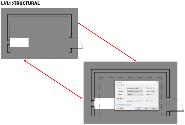
The result of changing the Level 1 Floor Plan's View Discipline to Structural, with the following View Range settings:
     Primary Range:
             Top Range: Level Above with 2300mm Offset
             Cut Plane: 1200mm
             Bottom Range: Unlimited
     View Depth: 
             Level: Unlimited

And lastly, the result of changing the Level 1 Floor Plan's View Discipline to Coordination, with the following View Range settings:
     Primary Range:
             Top Range: Level Above with 2300mm Offset
             Cut Plane: 1200mm
             Bottom Range: Unlimited
     View Depth: 
             Level: Unlimited


What can we then learn from the examples above? Create a dedicated Coordination Plan view, with the Discipline set to Coordination if any coordination needs to take place. Remember, the Coordination View Discipline is especially effective in a 3D view. Create and make use of filters to ensure turning services on and off is easy to do.

Monday, 13 June 2016

Alternative Visualization Methods

As Revit Recess is a blog investigating the workarounds in Revit, I have thought it would be apt to see what alternative methods one can use to create visualizations. In this entry we will investigate 5 alternative methods to create interesting visualizations in Revit, using only the default tools we get OOTB.

The first visualization example is to create a Mosaic using a combination of duplicated section views, each having their own and unique crop boundary, coupled with a visual style override for each view. The first image was created by duplicating a building section 11 times as a dependent. This allowed me to quickly change each dependent view's crop boundary in its parent view (Why can't we align or snap one crop boundary to another yet?). The challenge here was that if one changes the visual style of one view, all other dependent views' visual styles also change. 

To overcome the latter, all one needs to do is to duplicate each dependent view, as the crop boundary shape and location is retained. The second image shows all those duplicated views added together (Very much like adding Tetris blocks together - the views automatically aligns itself into position). 


The Mosaic visualization above can be taken even further: By creating a thin mosaic mass, with each mosaic section having its own shape and transparent colour, one can effectively add your own "filter" to a scene. Now this is where my ADD kicked in - What does the Refraction properties for materials really do? Below you will find the Refraction results for Air, Water, Alcohol, Quartz, Glass and Diamond. 


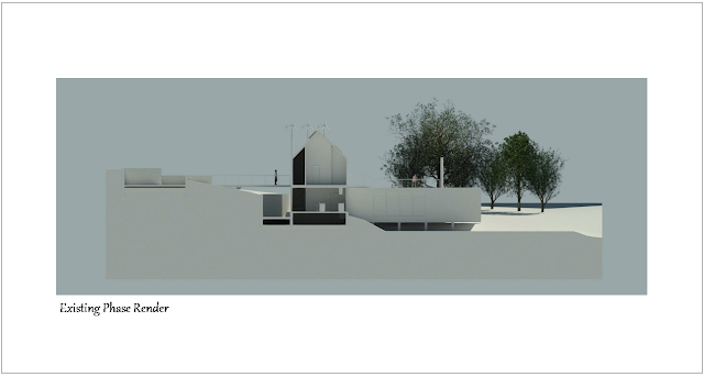
Modifying a scene's phasing properties and graphic overrides is however my favourite method: All elements in the scene, except for Planting, was added to the Existing Phase. The Existing Material was modified to a light grey.


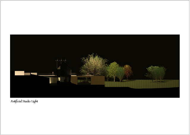
Another interesting visualization method is to artificially manipulate a night render scene using a single light source. You will notice no exterior or interior lighting fixtures are turned on - The single light source is a huge studio light with its Photometric properties bumped up to quite an extent, elevated approximately 50 meters above the toposurface.


Revit also has the ability to render a scene with a transparent background. Any image can then be superimposed on the Revit scene. As I firmly believe life is too short to be serious all of the time, here is an example of what I believe Armageddon will look like. Enjoy the rest of your week folks!