Search This Blog

Monday, 30 March 2015

Three 3 Second AutoCAD tips for Revit

Thanks to a client who old-schooled me with an awesome AutoCAD command called “OOPS”, I have decided to post a list of my three most useful AutoCAD command tips for Revit users. All of these commands can be used to prepare an AutoCAD drawing for Revit linking purposes.

1. AutoCAD command: "OOPS"

  • This is a very nice command to undo the most recent AutoCAD objects and lines you have deleted. As can be seen from the image below, I have selected the Sterile Supply room cupboards, sink, hand dryer and dividing wall, and will delete these items


  • I will now modify the shelving to run around the perimeter of the room, and add text as per the image below. 
  • If you realise that you made a mistake (i.e. deleting the room from the drawing), simply type the command “OOPS” into the AutoCAD command bar.
  • Your last deleted AutoCAD objects and lines will now be restored to their original position. Nifty, hey?


2. AutoCAD command: "FLATTEN"
  • More often than not, you will either generate a drawing in which you have hundreds if not thousands of line start and/or end points having a Z-axis offset. This typically happens when snapping an AutoCAD line to another which has an elevation specified. This will create huge problems in Revit, especially in Elevation and 3D views.

  • A quick and easy fix to this is to select all lines and type Flatten into the command bar. When prompted to remove Hidden Lines, select No. 

  • AutoCAD will now force all lines which has a z-value to be flattened to a z elevation of 0


3. AutoCAD command: "OVERKILL"
  • Yet again, most AutoCAD files, either created by yourself, or those received from the professional team might have multiple lines in the same location. This creates a file size problem both in AutoCAD, as well as in Revit. To quickly delete any and all overlapping lines, select all lines and type OVERKILL into the command bar


  • You will be able to select certain categories you would like to exclude (Ignore) from the operation

  • When selecting OK, in this example, I have deleted 89 duplicate lines, as well as 566 overlapping objects/segments. This is not a large AutoCAD project, so just imagine the advantages of working on a 20 000 sqm plus GLA project! Huge difference me thinks!

Wednesday, 25 March 2015

Model Faster - Part 1

It is the small things that makes life easier.

This will be the first of various entries detailing how to model faster in Revit. Some of the tips you might know about already and some you might have forgotten. 

This entry will focus on detailing in Revit, however the same principles applies to system families such as walls. We will test the time it takes to draw a simple cross with rounded corners.


The first image above is the drafting objective: Side lengths are 94mm, with corner radiuses of 20mm.

The second image was created by drawing the cross first (without any rounded corners). The radiuses were then added using the old conventional AutoCAD method of using fillet arcs. This method took 48 Seconds to complete, from starting the Detail Line command, to the completion of the object.

The last image was created by drawing the cross using the Detail Lines command, with the exception of enabling the Radius tickbox in the Options bar. This method cut the modelling time with more than 50%, being 22 seconds.

The videos below will show the two methods that were used.

Video 1: Fillet Arc command


Video 2: Radius enabled


Monday, 23 March 2015

Elements moving/jumping in view_Fix

Sometimes, not very often, I receive project files where the 3D geometry moves, or perhaps better described as "jumps around" when panning or zooming in a view. I believe this is one of the unexplained things that just sometimes happen on a project. Is there a workaround? The long answer is: Yes. The short answer is Y.

More often than not, the problem is localized to a specific view only. 

ZOOM 1

ZOOM 2

ZOOM 3

Instead of trying for hours to find out exactly what went wrong in the view, remember that Revit is a 3D BIM software tool with bi-directional associativity. In other words, your 3D model will exist in all views, unless it is deleted.

So, what would the workaround be?

First of all, you need to navigate to the affected view. Window-select all elements in the view and start your selection Filter command.

Filter out all 3D related categories, leaving only 2D annotations, such as your tags, text, detail lines, and the like.

These selected elements can now be copied to your Clipboard. Open another view, and delete the affected view from your project (You cannot delete an open view). Once a new view for that affected level has been created, you can Paste all the Clipboard items to the Same Place. This will ensure that you do not lose any work recreating a now healthy view. 

Thursday, 19 March 2015

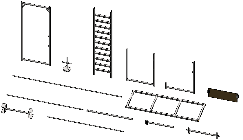
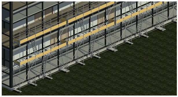
Parametric Revit Scaffolding

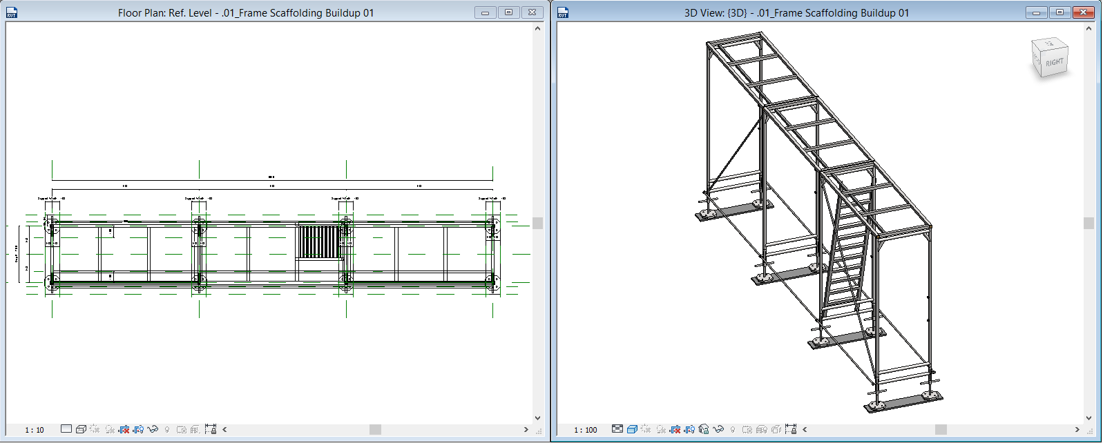
I have been researching a few scaffolding manufacturer’s technical drawings that are available on the internet, and came across a company called Varient Factory. This company provided quite a lot of detail regarding their frame scaffolding technical specifications, as well as erection details and procedures. You are more than welcome to visit their website, using the following link: http://www.variant-factory.eu/scaffolding/scaffolding-3


The following plan- and 3D view images will show the scaffolding as it is being erected:


Tuesday, 17 March 2015

Revit 2015 UR 7 for R2 Available for Download

The latest Update Release for Revit 2015 R2, UR7, is available for download.

Note: All relevant documentation such as Readme files and Product Enhancements documentation, will be updated once the official enhancement list is available. 


UPDATE 2015.03.27: Readme file and enhancement list links have been added below

Direct Download

Readme Documentation
Enhancements

Monday, 16 March 2015

Revit Recess Pie Chart

Today Revit Recess has breached the 1000 viewer mark! I would like to thank the all visitors (Especially the frequent readers) for their time and I hope you find my ramblings insightful, if not amusing at times. 

To celebrate the first 1000 views, three Pie Charts were created, containing the blog visitor statistics:


And lastly, the best pie chart of all: 

Sunday, 15 March 2015

Revit Planting RPC Source Files

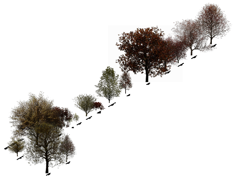
Instead of wasting time searching for the correct plants, trees and shrubs to add to your project, have a look at the following images. A Planting Source file was created that contains all of the OOTB Plants, Trees, and Shrubs. This complete source file is available for download as well as separate files focussing on the different Planting RPC types.

Feel free to let me know whether the download link works : Revit Planting RPC source files link


Tuesday, 10 March 2015

Project Location VS Project Position

Revit's Project Location and Project Position's functionality is misunderstood most of the time users just starting to learn Revit. In this entry, we will investigate what the effects are of changing the project's Base Point, as well as the project's Survey Point. In addition to the latter, what will happen if we move the project to a new location?

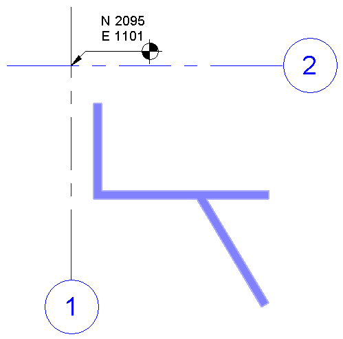
I have added a few walls to a clean project, enabled my Sun Path, and turned my Shadows on. A Spot Coordinate was also placed at my grid intersection.

The Location and Position settings can be found in the Manage Tab>Project Location panel.

When accessing the Location Settings, you will be able to specify the location of the project, i.e. affecting the sun's respective location (This is extracted from your lattitude and longitude values)
Should the project be re-positioned, via the Relocate Project command, the project base point will move, and the Survey Point will stay in place. The Project Base Point determines the project's location on the world map, using cadastral coordinates. The Survey Point is used for coordination between disciplines as well as to specify coordinates for exporting to another program, such as Autodesk Civil 3D.

Survey Point

Project Base Point

Below is the official Autodesk definition of a Project Base Point and a Survey Point:

"The project base point defines the origin (0,0,0) of the project coordinate system. It also can be used to position the building on site and for locating the design elements of a building during construction. Spot coordinates and spot elevations that reference the project coordinate system are displayed relative to this point."

"The survey point represents a known point in the physical world, such as a geodetic survey marker. The survey point is used to correctly orient the building geometry in another coordinate system, such as the coordinate system used in a civil engineering application."

If one now investigate the effects the survey point will have on an engineering drawing, one will see that the survey point plays an integral part in the coordination process. The project file was linked into an MEP template. The engineer will now Acquire the Coordinate System that was specified by the architect.

Notice how the MEP project coordinates updated from N2231, E-2733, to N2095, E1011. This is done to ensure that whenever any project file is linked into another, the specified coordinate system is retained and all files will be in the correct location.

Monday, 9 March 2015

MEP File Size Maintenance_Modelling

File size maintenance is extremely important in the MEP project environment. Due to the amount of consultant files (Revit and DWG) normally linked into a project, the amount of views (Both plan, ceiling, schedules, 3D, sections, elevations, sheets, etc.) being created, the project can become quite heavy and thus computer performance will start to suffer. There are quite a few remedial actions one can take to keep a MEP project file size as small as possible.

This entry will focus on a modelling method example. The basic principle of Revit, irrespective of being an Architectural, Mechanical, Electrical, Plumbing or Structural project, is not to over model. Too many complex geometrical shapes will decrease computer performance, as well as affect the overall project file size. 

We will be using the example of duct hangers as 3D objects and duct hangers as 2D objects in the Do-Nut-Stop project. A comparison will then be made between the file sizes.


Circular ducting will be placed on the curved line as indicated below.

One of the drawbacks to creating ducting on a curved route, it that one cannot natively draw ducting as a curve, nor can we draw ducting by picking lines. Thus the ducting will have to be drawn in sections. Using the curved line as a duct route placeholder, ducting can be drawn at sections of 1475mm using the curved line as a placement point. 

I have created a simple 3D hanger family which contains very simple geometry, with 7 parameter dimensions to drive the hanger diameter, offset from its level, etc. 

Krantz-type diffusers have been placed in the project as well 

The 3D hangers have been placed at equal intervals (One hanger supporting one duct segment). 

Even though the hangers looks extremely good in any view, when we look at the file size after only a few 3D hangers were placed, we will see that the file size is quite large: 10.5MB              

Should we rather decide to draw hangers as a 2D repeating detail, as per the image below, we will notice that the overall file size decreases with at least 2MB! You will have to make the decision: Do you really NEED to see hangers in 3D? What will it contribute to the overall file size? How will it affect your computer's performance, especially on large and complex project files? I will leave the decision up to you.