"P&ID Modeler streamlines the process for modeling in Revit based on P&IDs and ensures consistency between the P&ID drawing and the Revit model.
Use P&ID Modeler to:
- Enable collaboration between project team members, including re-use of data captured at earlier stages.
- Simplify the creation of the model from early stage schematic deliverables, by minimizing manual entry.
- Validate consistency between the 2D schematic and the 3D model.
P&ID Modeler is intended to replace the manual workflow of creating a 3D model with the guidance of a printed P&ID drawing. Use it to create a 3D piping model directly from a 2D P&ID. Status indicators make it easy to track what has been modeled and what remains to be modeled."- Autodesk
This is a step in the right direction. Autodesk has recently released an update for Revit called P&ID Modeler for Revit 2018.1. As highlighted in bold above, this update will not be a one-click-wonder to automatically convert a P&ID drawing to intelligent geometry.
So, how does this update work? This Revit Recess entry will take you through the steps.
1. The P&ID Modeller is only applicable for Revit 2018.1, and can only be downloaded through the Autodesk Desktop App.
One needs to either have received a link to collaborate with a P&ID drawing, or have access to Plant
3D to properly use this workflow. Through Plant3D, we can share the
entire P&ID model to the cloud. Collaboration > Project > Share Project.
The sharing of the P&ID drawing takes place over BIM360 Team.
We need to choose a Hub and Project folder to which the P&ID drawing must be uploaded. Obviously the project folder needs to be set up over BIM360 Team’s website first.
Depending on the file sizes and your internet connection, it might take some time
to upload these files.
As this is a BIM360 Team
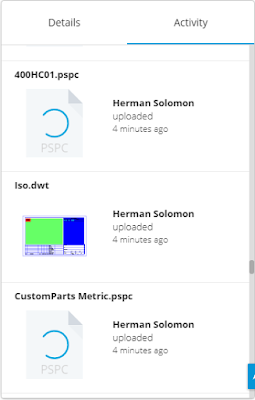
model now, the usual BIM 360 Team functionality is accessible, such as inviting team members, changing permission settings, viewing who has uploaded files, made changes, etc.
In Revit 2018.1
(Provided the add-in is installed), you will see the P&ID Modeller
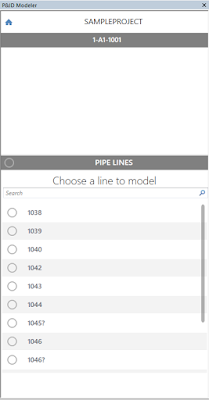
icon (Systems > P&ID Collaboration > P&ID Modeler). You will also see another panel window specific to the add-in. If you cant see the panel window, enable it by going to View > Windows > User Interface > P&ID Modeler.
Please note that to use the
add-in, you need to have an active C4R (Collaboration for Revit) license. Another note: I have found that trying to sign into your Autodesk Account through Revit does not work - Signing into your Autodesk Desktop App automatically signs you into Revit, which allows you to start the collaboration process. All that needs to be done now, is to select the P&ID project you would like to use in Revit.
We need to select a Plant 3D paper space layout which we would like to use in Revit. Note that you will struggle to access the drawing with a bad internet connection.
The Plant 3D model will
now contain all pipe segments complete with all their respective fittings,
valves, accessories, tags, etc.
When selecting a fitting
in a pipe segment, we will get a warning that Revit cannot map or match the
P&ID part to a Revit family. Similar to Fabrication Parts,
we have to tell Revit which family needs to be mapped to which P&ID
part
This can be defined
through the P&ID Modeler settings. The Revit families loaded into
your project will determine how the add-in automatically maps Plant to
Revit. It seems like the families which are highlighted in green has
common words in the family and type name, but the entire name does not
match (Although I have not yet confirmed this).
When selecting a pipe segment from the palette window,
Revit will identify and highlight the P&ID segment in dark blue – As the P&ID drawing also contained blue lines, it became a bit difficult to see where in the drawing I was. I
searched for a way to change these colours, but could not find it yet. Revit’s Pre-selection, Selection and Error
colours did not make a difference.
In a nutshell, you can either pick an existing Revit pipe and through the palette window, right click on a pipe segment and choose map existing. This will create a monitoring relationship between the Revit pipe segment and the P&ID pipe segment. Alternatively, you can sketch Revit pipe segments by just clicking on the P&ID pipe segment and drawing your pipe in the Revit view.
As stated in the introduction to this post, the idea behind the P&ID functionality is that the operator can visually see if he/she has modeled everything within the P&ID file by simply looking at the palette window.
Note: An unmapped segment/fitting/accessory will show
with a black line to the left side on the window panel, a mapped and unconnected piece in yellow with
green hatching, and a mapped and connected piece in solid green
This new update has certainly interested me, especially if we look at what other functionality can be created. Just imagine having the ability to convert an entire P&ID model complete with the correct equipment, fittings, valves and accessories with only a few clicks?
Have a good day folks!


No comments:
Post a Comment