As per Greg Hayslett's request for a tutorial on the creation of
a previous blog post: Revit LED Striplights,
herewith the steps to create it using both the Generic Line Based method, as
well as the Railing method.
Method 1: Strip Light as Line Based Family
Step 1: We need to create two families, the first being a
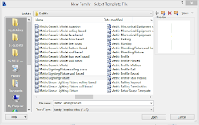
Metric Line Based family. Create a new family based on the Metric Generic Model Line Based family template.
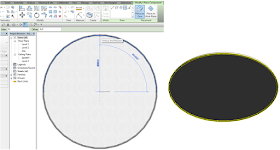
Step 2: Create a Sweep by picking the Reference Line as the path. Create a 10mm radius circle profile to
represent the LED tube. You can either now choose a Material for the tube, or Associate the Material parameter. This will allow you to change the tube material in the project environment.
Step 3: We need a light source to embed (Or nest) inside of
the line based family. Create a new family based on the Metric Lighting Fixture family template.
Step 4: Select the Light
Source and change the Light Source
Definition’s Shape Emittance to Line,
and the Light Distribution to Spherical.
Step 5: Load the Lighting
Fixture family into the Line Based Family.
Select the light source and edit the Type
Properties. Change the Initial
Intensity under the Photometrics area
to 2.00 Watt. Set the Initial Colour as
per your preference.
Step 6: Here is the trick:
If you have a straight ceiling line, you will be able to draw a LED tube
segment according to the correct size, and create either an array (Cringe) or
copy it along the straight path. When you get to a curved ceiling line, you
will have to use either the Inscribed- or
Circumscribed Polygon Draw tool. We can create a maximum of 32
individual line based segments per polygon
draw command. Any unnecessary LED tube segments can be deleted if required.
When enabling the Light
Source checkbox in the Visibility
Graphics command for Lighting
Fixtures, you will be able to see the “representation” of light diffusion
Method 2: Strip Light as Railing Family
Step 1: Create a new family based on the Metric Profile family template
Step 2: Using the Line command, create a 5mm radius profile to indicate the LED tube.
Step 3: For the light source, create a new family based on
the Metric Baluster Panel family
template.
Step 4: Nest the previously created Lighting Fixture Light Source family (Method 1 – Line based family)
into the Metric Baluster Panel family.
Position the Lighting Fixture family
accordingly.
Step 5: Load the Metric
Baluster Panel family, as well as the Rail Profile family into your project. Start the Railing command and duplicate a Railing type. Re-name the railing as Striplight_Railing or similar. Edit the Type Properties of the Striplight_Railing
family and edit the Rails. Add a Rail using the Rail Profile family, with a specified offset, using the Plastic, Transparent Autodesk Revit
material.
Step 6: Now it’s time to add the baluster (Light Source) to
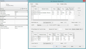
the rail. Edit the Balusters and
change the Baluster Family to the
previously created Metric Baluster Panel family.
You will have to change the Distance From
Previous value to get a perfect render representation. I found that in the
prvious post, a value of 230mm gave an acceptable result. Remember to set the Posts area for Start Post, Corner Post, and End
Post to None.
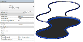
You will now be able to sketch the railing path using any of
the drawing tools you want. Remember to set the Base Offset of the rail to the required Base Offset.
· Note that if you set the Top Rail option in the rail Type
Properties to None, your rail
will “break”. The best bet would be to hide the Top Rail per construction view required.


No comments:
Post a Comment